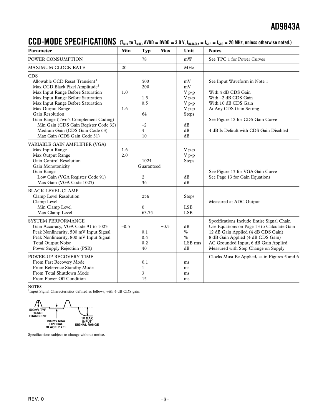
AD9843A specifications
The Analog Devices AD9843A is a high-performance, integrated analog-to-digital converter (ADC) designed for a variety of applications requiring precise signal conversion. This device boasts a 12-bit resolution, making it suitable for capturing fine details in complex signals. The AD9843A operates with a maximum sampling rate of up to 130 MSPS (mega samples per second), which allows it to handle fast-changing waveforms effectively, ideal for applications in the fields of telecommunications, instrumentation, and medical imaging.One of the standout features of the AD9843A is its dual-channel architecture, which enables simultaneous sampling of two input signals. This capability is particularly beneficial in applications such as radar and sonar systems, where capturing multiple input sources in parallel is critical. Furthermore, the ADC incorporates a high-speed programmable gain amplifier (PGA), providing adjustable gain settings to accommodate a wide range of signal amplitudes, ensuring optimal performance across various input conditions.
The AD9843A employs Differential Non-Linearity (DNL) and Integral Non-Linearity (INL) specifications, both of which contribute to its impressive accuracy and linearity. With a DNL of ±0.5 LSB (least significant bit) and an INL of ±1 LSB, the AD9843A minimizes distortion and enhances the fidelity of the digital representation of analog signals. Additionally, the device features low noise performance, which is essential for obtaining high-quality signal digitization, especially in sensitive applications where signal integrity is paramount.
Another key characteristic is the integrated sample-and-hold circuit that allows the ADC to capture input signals with minimal distortion during the conversion process. This design choice helps to stabilize the input signal, reducing the effect of sampling jitter. The AD9843A also provides various output data formats, including binary, gray code, and two's complement, which gives designers the flexibility to interface the ADC with different digital systems.
In terms of power consumption, the AD9843A is efficient, operating at a typical supply voltage of 5V. It offers a significant advantage for battery-operated devices by ensuring that the power requirements are kept low without compromising performance. With its combination of high throughput, low noise, and versatility, the Analog Devices AD9843A stands out as a robust solution for high-speed data acquisition systems, making it a preferred choice among engineers and designers across various industries.

