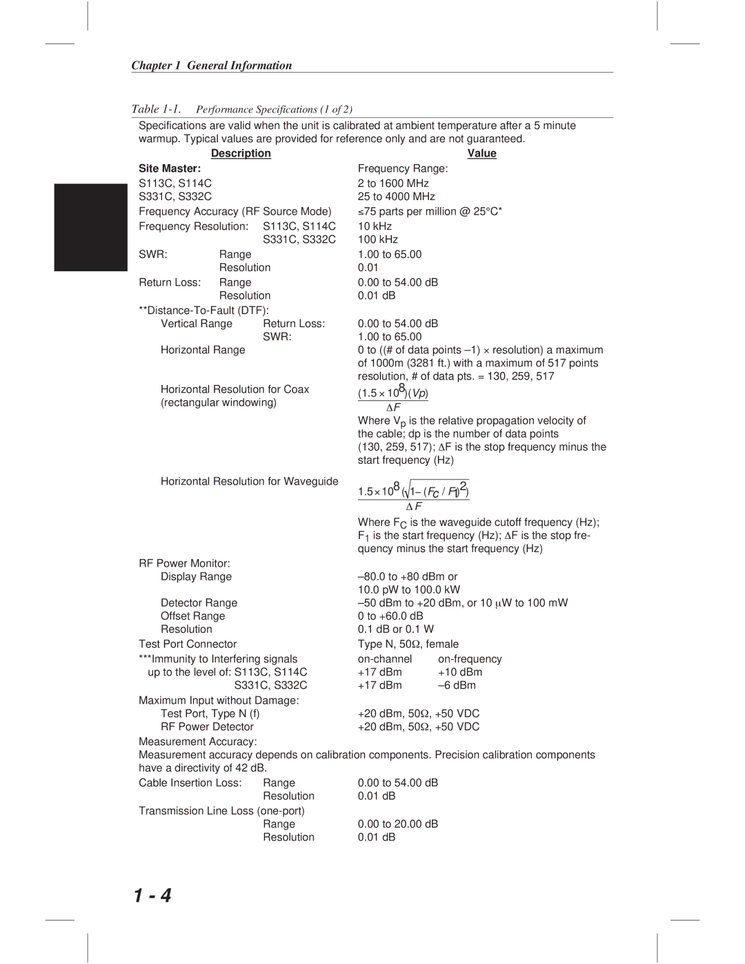
S113C, S332C, S114C, S331C specifications
Anritsu, a leader in test and measurement solutions, offers a range of handheld tools that cater to the needs of professionals in the RF and microwave industries. Among these tools are the Anritsu S331C, S114C, S332C, and S113C, each designed with unique features and technologies that make them suitable for various applications.The Anritsu S331C is a Cable and Antenna Analyzer that is particularly valued for its accuracy and ease of use. It operates within a frequency range of 3 MHz to 4 GHz, making it applicable for both wireless and microwave communication systems. One of its standout features is the built-in Time Domain Reflectometry (TDR) function, which allows technicians to pinpoint faults in cables quickly. The S331C's intuitive touch-screen interface ensures seamless operation, while its lightweight design allows for portability in the field.
On the other hand, the Anritsu S114C is a versatile handheld RF power meter that can measure a wide range of power levels and frequencies. Its exceptional measurement accuracy and broad dynamic range make it suitable for various applications, from network testing to maintenance. It supports both peak and average power measurements, providing users with the flexibility to adapt to different testing scenarios. The S114C also features a memory function that allows users to store and recall measurement data easily.
The S332C model is designed for more advanced applications, offering vector network analysis capabilities. Operating within a frequency range of 5 kHz to 4 GHz, it is used for characterizing components such as filters, amplifiers, and cables. The S332C features a high-resolution display and supports automated measurements, making it a powerful tool for engineers involved in the design and validation of RF components.
Lastly, the Anritsu S113C is an excellent choice for professionals requiring a compact and efficient solution for insertion loss and return loss measurements. This analyzer covers a frequency range of 5 kHz to 4 GHz and is especially suited for testing antennas and RF components. The S113C's lightweight design, combined with its user-friendly interface, allows operators to conduct measurements easily in various environments, ensuring high performance and reliability.
In summary, the Anritsu S331C, S114C, S332C, and S113C represent a comprehensive suite of handheld analyzers that cater to diverse needs in the RF and microwave sectors. With features like TDR function, RF power measurements, vector network analysis, and a focus on portability, these instruments are essential tools for professionals looking to enhance their testing capabilities and ensure high-quality network performance.

