Anritsu S114C, S113C, S332C, S331C InstaCal Module Verification, Termination Method, Offset Method

Models: S113C S332C S114C S331C

1 95
Download 95 pages 26 Kb
Page 46
Image 46

Chapter 3 Getting Started

InstaCal Module Verification

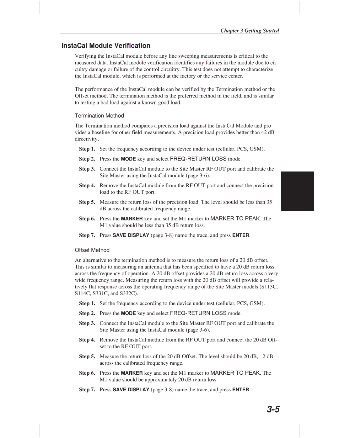
Verifying the InstaCal module before any line sweeping measurements is critical to the measured data. InstaCal module verification identifies any failures in the module due to cir- cuitry damage or failure of the control circuitry. This test does not attempt to characterize the InstaCal module, which is performed at the factory or the service center.

The performance of the InstaCal module can be verified by the Termination method or the Offset method. The termination method is the preferred method in the field, and is similar to testing a bad load against a known good load.

Termination Method

The Termination method compares a precision load against the InstaCal Module and pro- vides a baseline for other field measurements. A precision load provides better than 42 dB directivity.

Step 1. Set the frequency according to the device under test (cellular, PCS, GSM). Step 2. Press the MODE key and select FREQ-RETURN LOSS mode.

Step 3. Connect the InstaCal module to the Site Master RF OUT port and calibrate the Site Master using the InstaCal module (page 3-6).

Step 4. Remove the InstaCal module from the RF OUT port and connect the precision load to the RF OUT port.

Step 5. Measure the return loss of the precision load. The level should be less than 35 dB across the calibrated frequency range.

Step 6. Press the MARKER key and set the M1 marker to MARKER TO PEAK. The M1 value should be less than 35 dB return loss.

Step 7. Press SAVE DISPLAY (page 3-8) name the trace, and press ENTER.

Offset Method

An alternative to the termination method is to measure the return loss of a 20 dB offset. This is similar to measuring an antenna that has been specified to have a 20 dB return loss across the frequency of operation. A 20 dB offset provides a 20 dB return loss across a very wide frequency range. Measuring the return loss with the 20 dB offset will provide a rela- tively flat response across the operating frequency range of the Site Master models (S113C, S114C, S331C, and S332C).

Step 1. Set the frequency according to the device under test (cellular, PCS, GSM). Step 2. Press the MODE key and select FREQ-RETURN LOSS mode.

Step 3. Connect the InstaCal module to the Site Master RF OUT port and calibrate the Site Master using the InstaCal module (page 3-6).

Step 4. Remove the InstaCal module from the RF OUT port and connect the 20 dB Off- set to the RF OUT port.

Step 5. Measure the return loss of the 20 dB Offset. The level should be 20 dB, ￿2 dB across the calibrated frequency range.

Step 6. Press the MARKER key and set the M1 marker to MARKER TO PEAK. The M1 value should be approximately 20 dB return loss.

Step 7. Press SAVE DISPLAY (page 3-8) name the trace, and press ENTER.

3-5

Page 46
Image 46
Anritsu S114C, S113C, S332C, S331C manual InstaCal Module Verification, Termination Method, Offset Method

S113C, S332C, S114C, S331C specifications

Anritsu, a leader in test and measurement solutions, offers a range of handheld tools that cater to the needs of professionals in the RF and microwave industries. Among these tools are the Anritsu S331C, S114C, S332C, and S113C, each designed with unique features and technologies that make them suitable for various applications.

The Anritsu S331C is a Cable and Antenna Analyzer that is particularly valued for its accuracy and ease of use. It operates within a frequency range of 3 MHz to 4 GHz, making it applicable for both wireless and microwave communication systems. One of its standout features is the built-in Time Domain Reflectometry (TDR) function, which allows technicians to pinpoint faults in cables quickly. The S331C's intuitive touch-screen interface ensures seamless operation, while its lightweight design allows for portability in the field.

On the other hand, the Anritsu S114C is a versatile handheld RF power meter that can measure a wide range of power levels and frequencies. Its exceptional measurement accuracy and broad dynamic range make it suitable for various applications, from network testing to maintenance. It supports both peak and average power measurements, providing users with the flexibility to adapt to different testing scenarios. The S114C also features a memory function that allows users to store and recall measurement data easily.

The S332C model is designed for more advanced applications, offering vector network analysis capabilities. Operating within a frequency range of 5 kHz to 4 GHz, it is used for characterizing components such as filters, amplifiers, and cables. The S332C features a high-resolution display and supports automated measurements, making it a powerful tool for engineers involved in the design and validation of RF components.

Lastly, the Anritsu S113C is an excellent choice for professionals requiring a compact and efficient solution for insertion loss and return loss measurements. This analyzer covers a frequency range of 5 kHz to 4 GHz and is especially suited for testing antennas and RF components. The S113C's lightweight design, combined with its user-friendly interface, allows operators to conduct measurements easily in various environments, ensuring high performance and reliability.

In summary, the Anritsu S331C, S114C, S332C, and S113C represent a comprehensive suite of handheld analyzers that cater to diverse needs in the RF and microwave sectors. With features like TDR function, RF power measurements, vector network analysis, and a focus on portability, these instruments are essential tools for professionals looking to enhance their testing capabilities and ensure high-quality network performance.