7. PROGRAM DOWN LOAD
7.3 DOWN LOAD PROCEDURE
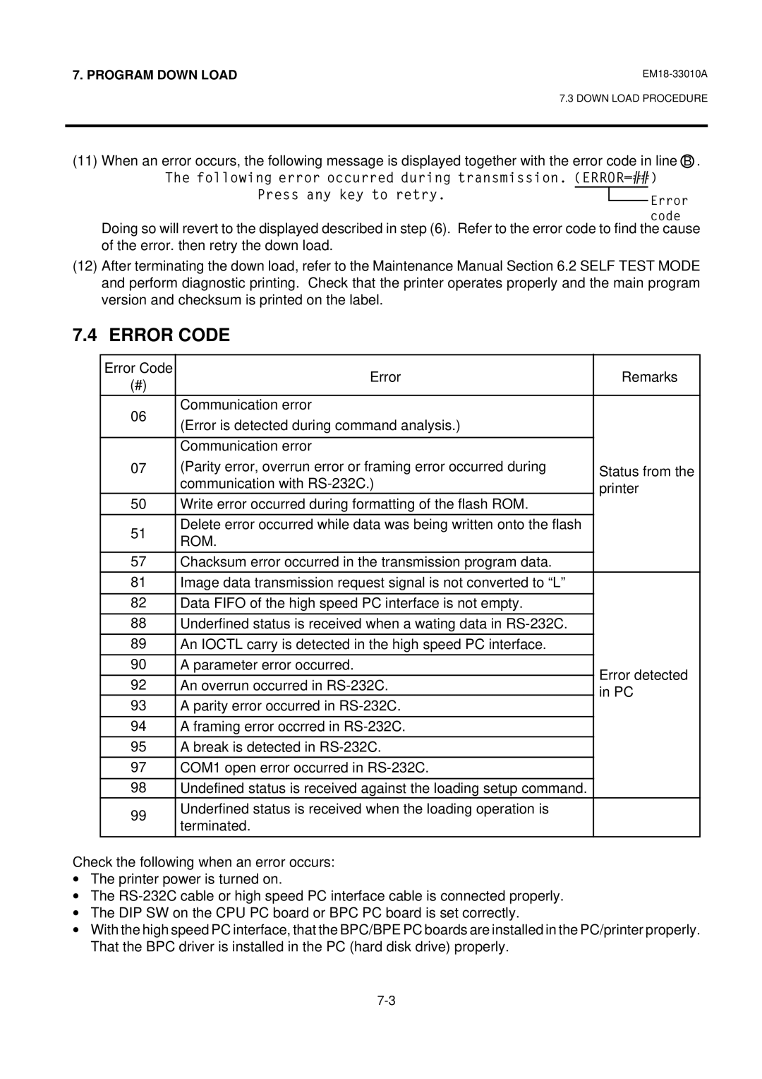
(11)When an error occurs, the following message is displayed together with the error code in line B .
The following error occurred during transmission. (ERROR=##)
Press any key to retry.
Doing so will revert to the displayed described in step (6). Refer to the error code to find the cause of the error. then retry the down load.
(12)After terminating the down load, refer to the Maintenance Manual Section 6.2 SELF TEST MODE and perform diagnostic printing. Check that the printer operates properly and the main program version and checksum is printed on the label.
7.4 ERROR CODE
Error Code | Error | Remarks | |
(#) | |||
|
| ||
|
|
| |
06 | Communication error |
| |
(Error is detected during command analysis.) |
| ||
|
| ||
|
|
| |
| Communication error |
| |
07 | (Parity error, overrun error or framing error occurred during | Status from the | |
| communication with | printer | |
50 | Write error occurred during formatting of the flash ROM. |
| |
|
|
| |
51 | Delete error occurred while data was being written onto the flash |
| |
ROM. |
| ||
|
| ||
|
|
| |
57 | Chacksum error occurred in the transmission program data. |
| |
|
|
| |
81 | Image data transmission request signal is not converted to “L” |
| |
|
|
| |
82 | Data FIFO of the high speed PC interface is not empty. |
| |
|
|
| |
88 | Underfined status is received when a wating data in |
| |
|
|
| |
89 | An IOCTL carry is detected in the high speed PC interface. |
| |
|
|
| |
90 | A parameter error occurred. | Error detected | |
|
| ||
92 | An overrun occurred in | ||
in PC | |||
93 | A parity error occurred in | ||
| |||
|
|
| |
94 | A framing error occrred in |
| |
|
|
| |
95 | A break is detected in |
| |
|
|
| |
97 | COM1 open error occurred in |
| |
|
|
| |
98 | Undefined status is received against the loading setup command. |
| |
99 | Underfined status is received when the loading operation is |
| |
terminated. |
| ||
|
| ||
|
|
|
Check the following when an error occurs:
∙The printer power is turned on.
∙The
∙The DIP SW on the CPU PC board or BPC PC board is set correctly.
∙With the high speed PC interface, that the BPC/BPE PC boards are installed in the PC/printer properly. That the BPC driver is installed in the PC (hard disk drive) properly.
