3. INSTALLATION PROCEDURE FOR THE OPTIONAL EQUIPMENT
EM18-33010A
SVO7A1003: Nov. 21 ’97
3.2 CUTTER MODULE
7.Install the cutter unit with the attached screws (cutter attaching screw,
When installing the cutter, make sure that the cutter guide is not in contact with the platen. If it is, print failure or noise may be caused.
Fig.
8.Remove the motor cover. (See Fig.
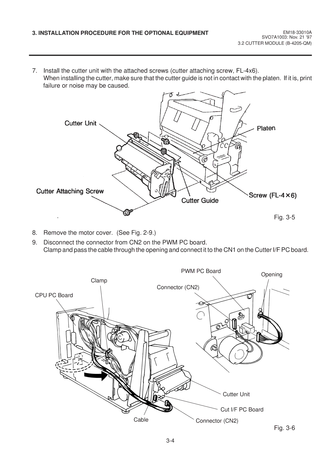
9.Disconnect the connector from CN2 on the PWM PC board.
Clamp and pass the cable through the opening and connect it to the CN1 on the Cutter I/F PC board.
PWM PC Board
Clamp
Connector (CN2)
CPU PC Board
Opening
| Cutter Unit |
| Cut I/F PC Board |
Cable | Connector (CN2) |
Fig.