3. INSTALLATION PROCEDURE FOR THE OPTIONAL EQUIPMENT
3.3 MEMORY MODULE
3.3 MEMORY MODULE
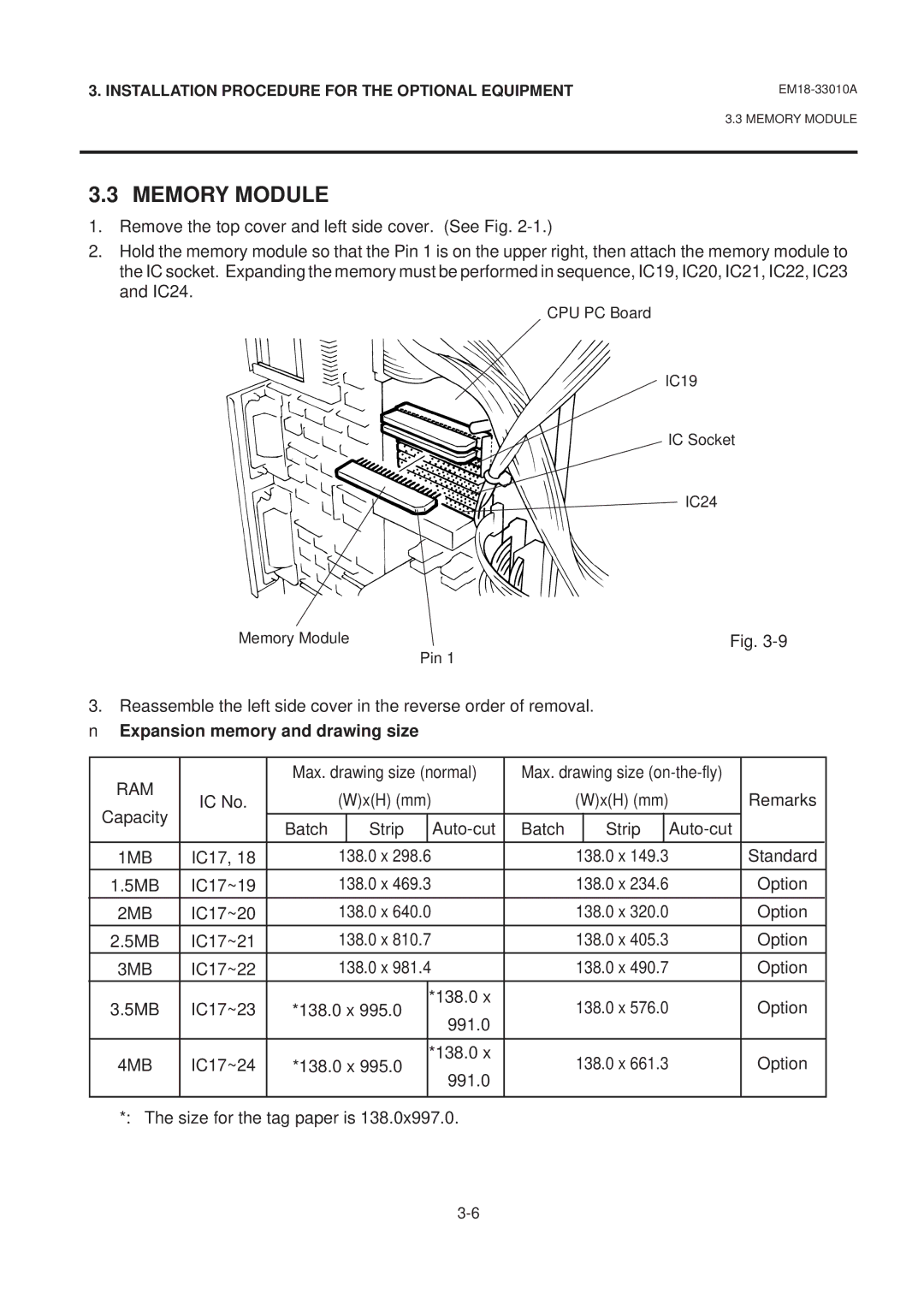
1.Remove the top cover and left side cover. (See Fig.
2.Hold the memory module so that the Pin 1 is on the upper right, then attach the memory module to the IC socket. Expanding the memory must be performed in sequence, IC19, IC20, IC21, IC22, IC23 and IC24.
CPU PC Board
IC19
IC Socket
IC24
Memory Module | Fig. |
| Pin 1 |
3. Reassemble the left side cover in the reverse order of removal.
■Expansion memory and drawing size
RAM |
| Max. drawing size (normal) | Max. drawing size |
| ||||||||
IC No. |
| (W)x(H) (mm) |
|
| (W)x(H) (mm) |
| Remarks | |||||
Capacity |
|
|
|
| ||||||||
|
|
|
|
|
|
|
|
|
|
|
| |
| Batch |
| Strip |
| Batch |
| Strip |
|
| |||
|
|
|
|
|
|
| ||||||
|
|
|
|
|
|
|
|
|
|
|
|
|
1MB | IC17, 18 |
| 138.0 x 298.6 |
|
| 138.0 x 149.3 |
| Standard | ||||
|
|
|
|
|
|
|
|
|
|
|
|
|
1.5MB | IC17~19 |
| 138.0 x 469.3 |
|
| 138.0 x 234.6 |
| Option | ||||
|
|
|
|
|
|
|
|
|
|
|
|
|
2MB | IC17~20 |
| 138.0 x 640.0 |
|
| 138.0 x 320.0 |
| Option | ||||
|
|
|
|
|
|
|
|
|
| |||
2.5MB | IC17~21 |
| 138.0 x 810.7 |
|
| 138.0 x 405.3 |
| Option | ||||
3MB | IC17~22 |
| 138.0 x 981.4 |
|
| 138.0 x 490.7 |
| Option | ||||
|
|
|
|
|
|
|
|
|
|
|
| |
3.5MB | IC17~23 | *138.0 x 995.0 | *138.0 x |
| 138.0 x 576.0 |
| Option | |||||
| 991.0 |
|
| |||||||||
|
|
|
|
|
|
|
|
|
|
|
| |
|
|
|
|
|
|
|
|
|
|
|
| |
4MB | IC17~24 | *138.0 x 995.0 | *138.0 x |
| 138.0 x 661.3 |
| Option | |||||
| 991.0 |
|
| |||||||||
|
|
|
|
|
|
|
|
|
|
|
| |
|
|
|
|
|
|
|
|
|
|
|
|
|