3. INSTALLATION PROCEDURE FOR THE OPTIONAL EQUIPMENT
3.2 CUTTER MODULE
3.2 CUTTER MODULE (B-4205-QM)
Description | Q’ty/Unit | Description | Q’ty/Unit |
|
|
|
|
Cutter Unit | 1 | Cutter Attaching Screw | 2 |
|
|
|
|
Cutter Cover | 1 | Screw | 1 |
|
|
|
|
1 | Cleaner | 1 | |
|
|
|
|
NOTE: For the
1.Remove the top cover and left side cover. (See Fig.
2.Remove the I/F PC board. (See Fig.
3.Remove the front plate. (See Fig.
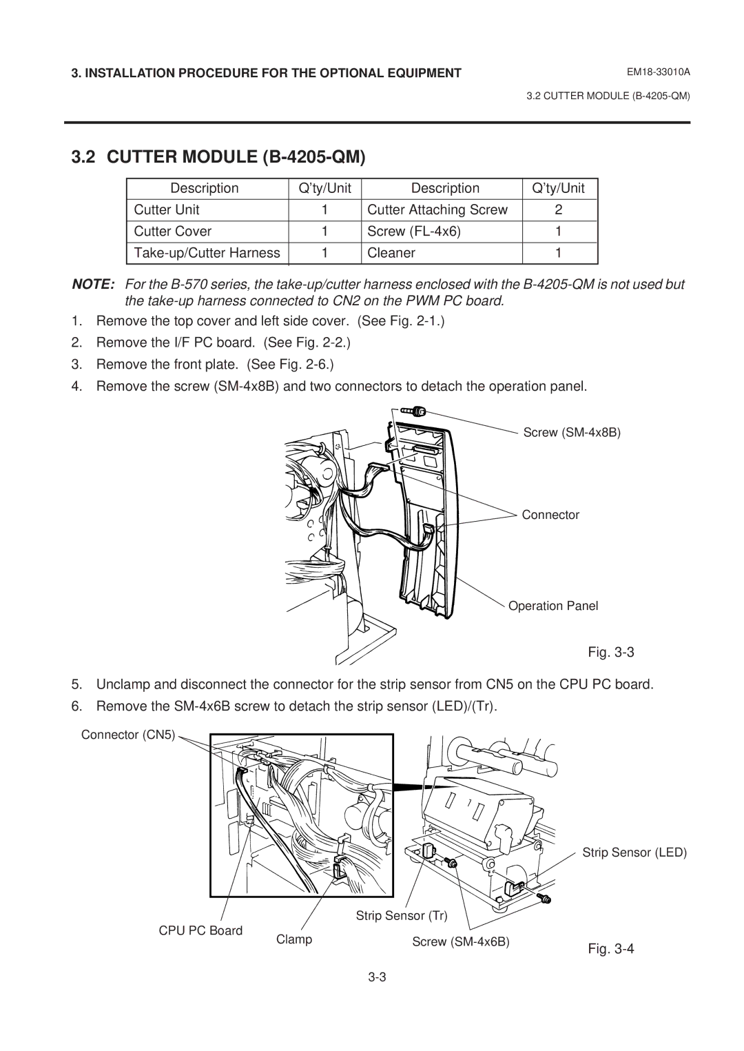
4.Remove the screw
Screw
Connector
Operation Panel
Fig.
5.Unclamp and disconnect the connector for the strip sensor from CN5 on the CPU PC board.
6.Remove the
Connector (CN5)
Strip Sensor (LED)
| Strip Sensor (Tr) |
|
CPU PC Board | Screw |
|
Clamp | Fig. | |
|
|
