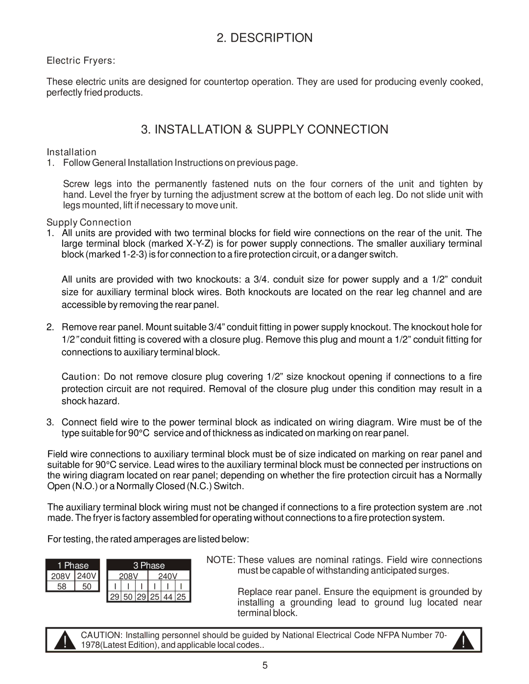
EF-30 specifications
The APW Wyott EF-30 is a highly efficient countertop electric fryer designed to meet the demands of today's busy commercial kitchens. Known for its reliability and performance, the EF-30 offers a range of features that appeal to restaurant owners and chefs seeking to maximize their cooking capabilities while minimizing operational costs.One of the standout features of the APW Wyott EF-30 is its generous cooking capacity. With a large tank that can hold up to 30 pounds of oil, the fryer allows for frying large batches of food at once, making it ideal for high-volume operations. This capability ensures that chefs can keep up with customer demand during peak hours, resulting in reduced wait times and improved service.
The EF-30 is equipped with advanced heating technologies that enhance performance and energy efficiency. The fryer utilizes a powerful, immersion-style heating element that heats the oil quickly and evenly, ensuring consistent cooking results across all types of food. The adjustable temperature control allows chefs to set the desired frying temperature, providing flexibility for various menu items from crispy french fries to battered fish.
Safety features are paramount in the design of the APW Wyott EF-30, making it a reliable choice for any kitchen. The fryer includes a built-in thermostat that prevents overheating, ensuring that the oil remains at a safe temperature. An easy-access drain valve is also included, allowing for safe and efficient oil changes without the risk of spills or splatters.
In terms of construction, the EF-30 boasts a durable stainless-steel body that not only provides a sleek appearance but also enhances the unit's longevity and resistance to corrosion. The fryer's compact countertop design makes it suitable for kitchens with limited space, and its portability allows for easy relocation if necessary.
Maintenance of the APW Wyott EF-30 is straightforward, thanks to its removable fry pot and easy-access components. This feature simplifies the cleaning process, helping to maintain high hygiene standards in the kitchen.
Overall, the APW Wyott EF-30 combines performance, safety, and durability, making it a top choice for restaurants and foodservice operations looking to boost their frying capabilities while keeping operational efficiency at the forefront. With its impressive features and user-friendly design, the EF-30 is indeed a valuable asset for any culinary establishment.

