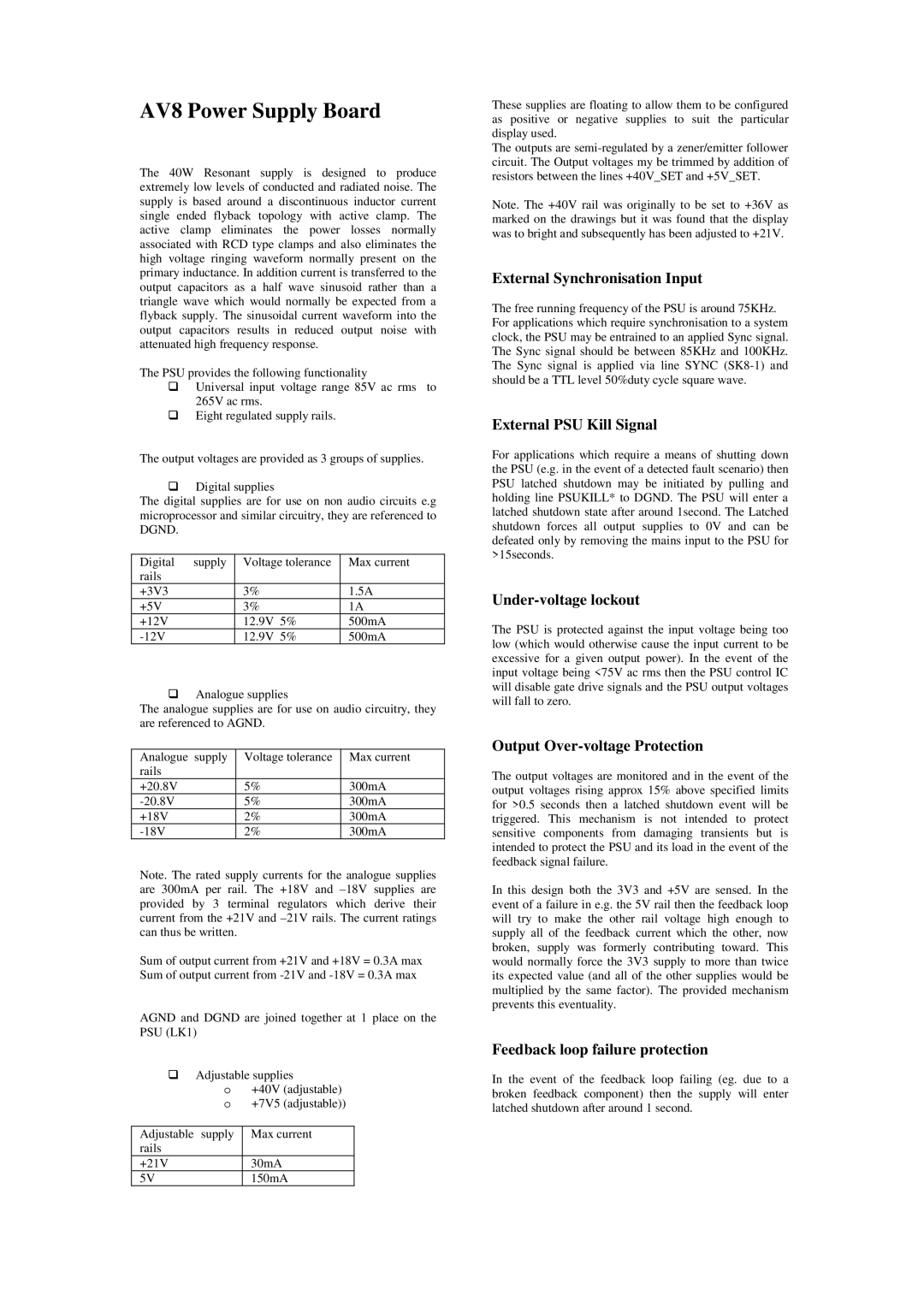
AV8 specifications
The Arcam AV8 is a high-performance audio-video receiver that has garnered attention for its exceptional sound quality and versatile features, making it a sought-after option for both audiophiles and home theater enthusiasts. Designed to provide an immersive viewing experience, the AV8 is equipped with a range of technologies that enhance its performance.One of the standout features of the Arcam AV8 is its support for high-definition audio formats. The receiver can decode various lossless audio formats, including Dolby TrueHD and DTS-HD Master Audio, allowing users to experience studio-quality sound. This capability is complemented by its advanced digital signal processing, which ensures that the audio output is clear and dynamic, enhancing the overall entertainment experience.
The AV8 is built with an emphasis on connectivity and flexibility. It boasts multiple HDMI inputs and outputs, facilitating seamless connections to a variety of devices such as Blu-ray players, gaming consoles, and streaming devices. With support for 4K video pass-through, the AV8 is future-proofed for high-definition content, ensuring compatibility with the latest video technologies.
Another notable aspect of the Arcam AV8 is its user-friendly interface. The receiver is equipped with an intuitive on-screen display that simplifies navigation and setup. Additionally, Arcam has incorporated room calibration technology, which analyzes the acoustic properties of the listening environment and adjusts the audio output accordingly. This feature allows for optimal sound reproduction, tailored to the specific characteristics of the room.
The build quality of the AV8 is exceptional; it features a robust chassis designed to minimize vibration and interference, ensuring high-fidelity sound reproduction. The receiver is designed for ease of use, with remote control functionality and smart home integration options, making it convenient to operate alongside other devices.
In summary, the Arcam AV8 is a powerful AV receiver that combines high-definition audio capabilities, extensive connectivity options, and user-friendly features. With its strong emphasis on sound quality and innovative technologies, it stands out in the competitive landscape of home theater equipment, catering to the discerning tastes of audio enthusiasts and casual users alike. Whether for music or movie playback, the AV8 offers a compelling solution for those seeking an elevated audio-visual experience.
