Copyright Notice
Disclaimer
English
Motherboard Layout
Panel
LAN Port LED Indications
Activity/Link LED
Introduction
Package Contents
Specifications
USB3.0
Connector
Audio
Rear Panel I/O
Hardware
Bios Feature
Unique Feature
Support CD
FCC, CE, Whql
Certifications
English
English
English
Installation
Pre-installation Precautions
Screw Holes
CPU Installation
Black line
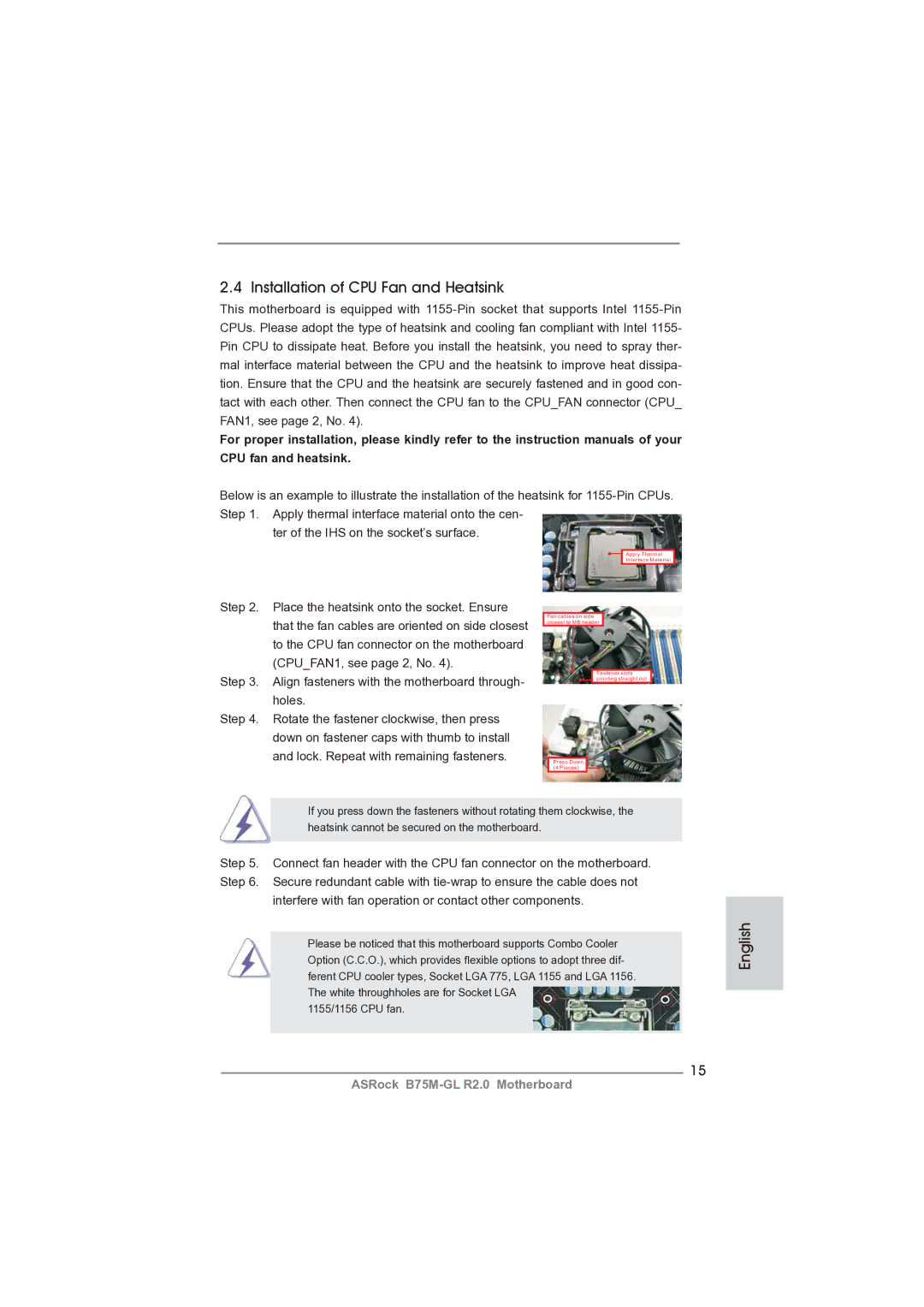
Installation of CPU Fan and Heatsink
Installing a Dimm
Installation of Memory Modules Dimm
Expansion Slots PCI and PCI Express Slots
Installing an expansion card
CrossFireXTM and Quad CrossFireXTM Operation Guide
Installing Two CrossFireXTM-Ready Graphics Cards
CrossFire Bridge
For Windows 7 / VistaTM OS
Driver Installation and Setup
Install the required drivers to your system
For Windows XP OS
English
Dual Monitor and Surround Display Features
Dual Monitor Feature
Sub port DVI-D port
For Windows XP / XP 64-bit OS
Surround Display Feature
What is HDCP?
For Windows 7 / 7 64-bit / VistaTM / VistaTM 64-bit OS
Hdcp Function
Advanced Super IO Configuration CIR Controller Enabled
ASRock Smart Remote Installation Guide
Install Multi-Angle CIR Receiver to the front USB port
Make sure the option CIR Controller is setting at Enabled
CIR sensors in different angles
Clear Cmos Jumper
Jumpers Setup
Jumper
Description
Onboard Headers and Connectors
Two USB 2.0 headers on this
USB 2.0 Headers Besides four default USB
Optional wireless transmitting
Connect the remote controller
System Panel Header
Several system front panel
Functions
Ground pin ATX Power Connector Please connect an ATX power
CPU Fan Connectors
Cable to the connector
Match the black wire to
Serial port Header This COM1 header supports a
English Driver Installation Guide
Installing Windows XP / XP 64-bit Without RAID Functions
ATX 12V Power Connector Please connect an ATX
Install Windows XP / XP 64-bit OS on your system
Software Support CD information
Bios Information
Einführung
Kartoninhalt
Deutsch
Spezifikationen
An der Rückseite
Anschlüsse
CD d’assistance
Einzigartige
Eigenschaft Siehe Vorsicht
Warnung
Zertifizierungen
Deutsch
Deutsch
Deutsch
Einstellung der Jumper
Jumper Einstellun Beschreibung
Cmos löschen
Integrierte Header und Anschlüsse
Optionales, drahtloses Sende
USB 2.0-Header
USB 3.0-Header
Dieser Header unterstützt ein
System Panel-Header
Mehrere Funktion der
Systemvorderseite
ATX-Netz-Header
Gehäuselautsprecher-Header Schließen Sie den
Diesen Header an
Gehäuse und Strom lüfteranschlüsse
Wird verwendet, um ein
ATX 12V Anschluss Bitte schließen Sie an diesen
Anschluss die ATX
Stromversorgung an
BIOS-Information
Contenu du paquet
Français
Spécifications
Panneau arrière
USB
Connecteurs
Unique Voir Attention
Caractéristique
Système
Surveillance
Français
Français
Français
Français
Réglage des cavaliers
Le cavalier Description
Effacer la Cmos
En-têtes et Connecteurs sur Carte
Sur cette carte mère. Chaque
En-tête USB
Par défaut sur le panneau E/S
Il y a deux embases USB
Système frontal
En-tête du panneau système Cet en-tête permet d’utiliser
De l’UC
En-tête du haut-parleur Veuillez connecter le De châssis
En-tête
Connecteur pour châssis et ventilateur
En-tête de port COM Cette en-tête de port COM est
Connecteur ATX Veuillez connecter une unité
’alimentation électrique ATX
12V sur ce connecteur
Informations sur le Bios Informations sur le CD de support
Introduzione
Contenuto della confezione
Italiano
Specifiche
Pannello
Posteriore I/O
Connettori
Speciale Vedi Attenzione
CD di
Supporto
Caratteristica
Certificazioni
Compatibilità
Attenzione
Italiano
Italiano
Italiano
Setup dei Jumpers
Resettare la Cmos
Jumper Settaggio del Jumper
Collettori e Connettori su Scheda
Intestazioni USB 2.0. Ciascuna
Collettore USB Oltre alle quattro porte USB
Predefinite nel pannello I/O, la
Scheda madre dispone di due
Diverse funzioni di sistema
Collettore pannello di sistema
Connettore alimentazione ATX Collegare la sorgente
’alimentazione ATX a questo
Connettore
Utilizzato per supportare il
Connettore ATX 12 Collegare un alimentatore ATX
A questo connettore
Collettore porta COM Questo collettore porta COM è
Italiano
Introducción
Contenido de la caja
Español
Especificación
Conectores
Entrada/Salida
De Panel
Trasero
CD de soport
Característica
Única
Certificaciones
Atención
Español
Español
Español
Setup de Jumpers
Jumper Setting
Limpiar Cmos
Cabezales y Conectores en Placas
Esta base de conexiones se
Recepción wireless opcional
Cabezal USB
Infrarrojos de transmisión y
Restablecer interruptor de restablecimiento
Cabezal de panel de sistema
Sistema
Pwrbtn interruptor de alimentación
Cabezal de alimentación ATX Conecte la fuente de
Cabezal del puerto COM Este cabezal del puerto COM
Cabezal de alimentación ATX Conecte la fuente de
Alimentación ATX 12V a su
Cabezal
Bios Información Información de Software Support CD
Введение
См. ОСТОРОЖНО, пункт
Платформа
Процессор
См. ОСТОРОЖНО, пункт Набор микросхем
100
101
Внимание
102
103
104
105
Перемычка Установка Описание
106
107
Колодки и разъемы на плате
Колодка USB
108
Reset кнопка сброса
109
Pwrbtn кнопка питания
Контакты 1-3 подключены
110
Pled индикатор питания системы
Hdled индикатор активности жесткого диска
Колодка питания ATX
111
112
Информация о Bios
113
Introdução
Este pacote contém
Português
114
Especificações
Pelo painel
115
Áudio
Entrada/Saída
Monitor do HW
116
CD de suporte
Funcionalidade
Certificações
117
Sistema
Operacional
118
119
120
Restaurar Cmos
Configuração dos Jumpers
121
JumperConfiguração
122
Conectores
123
124
Conector do painel do sistema
Funções do painel frontal do
125
Conector de porta de série Este conector COM1 suporta
126
Conector de força do ATX Ligue a fonte de alimentação
ATX 12V neste conector
127
Informações da Bios Informações do CD de Suporte
128
Türkçe
129
Arka Panel
Türkçe
130
Ses
131
Uyari
132
133
134
135
136
Jumper Ayar
CMOS’u temizleme
137
138
139
Sistem Paneli Fişi
Işlevini barındırır
Siyah kabloyu toprak pinine
140
CPU Fan Konektörü
Lütfen fan kablolarını CPU
141
Seri port Fişi
Kasaya Yetkisiz Erişim Fişi
142
Bios Bilgileri Yazılım Destek CD’si bilgileri
제품소개
143
시리얼 ATA Sata 데이터 케이블 2 개 선택 사양 차폐 1 개
144
145
146
147
인증서
ErP/EuP 지원 ErP/EuP 지원 전원 공급기가 요구됨 주의 21 참조
148
149
점퍼세팅
150
Cmos 초기화
151
152
153
시스템 콘넥터
능을 지원하기 위한 것입니다
154
155
156
시스템 바이오스 정보 소프트웨어 지원 CD 정보
157
Micro ATX フォームファクター 9.6-in x 8.4-in, 24.4 cm x 21.3 cm
I/O パネルシールド
158
159
160
ケースオープン検出
161
162
163
164
165
ジャンパ設定
166
オンボードのヘッダとコネクタ類。
167
168
シャーシおよび電源ファンコネクタ
169
170
このマザーボードは Microsoft Windows 7 / 7 64-bit / VistaTM / VistaTM
171
172
主板簡介
173
主板規格
高保真音頻插孔:音頻輸入 / 前置喇叭 / 麥克風
174
華擎即時開機功能
175
176
警告!
10、SmartView 是 Internet 瀏覽器的一項新功能,它作為 IE 的智能起始頁
177
178
179
跳線設置
180
板載接頭和接口
USB 3.0 擴展接頭
181
開啟前置麥克風。
182
CPU 風扇接頭
183
184
支持光盤信息
185
電子信息產品污染控制標示
186
Micro ATX 規格 9.6 英吋 x 8.4 英吋 , 24.4 公分 x 21.3 公分
兩條 Serial Atasata 數據線 選配 一塊 I/O 擋板
Dimm 插槽
187
USB 後置 USB 接口,支援 USB 1.0/2.0/3.0 到 5Gb/s 前置 USB
188
高清晰音效插孔:音效輸入 / 前置喇叭 / 麥克風
SATA3 6.0Gb/s 接頭,支援 NCQ, Ahci 和熱插拔功能
189
190
191
192
193
194
195
196
接頭。
197
Bios 訊息
198
本主板支援各種微軟 Windows 操作系統:Microsoft Windows 7/7 64 位元
Penjelasan
Isi Paket
199
200
Spesifikasi
201
Papan Belakang
Penghubung
Fitur Unik
Ciri-ciri Bios
202
Sokongan CD
203
Sertifikasi
ErP/EuP Ready memerlukan catu daya ErP/EuP ready
204
Installing OS on a HDD Larger Than 2TB in Ahci Mode