15 . System panel connector (20-pin PANEL1)

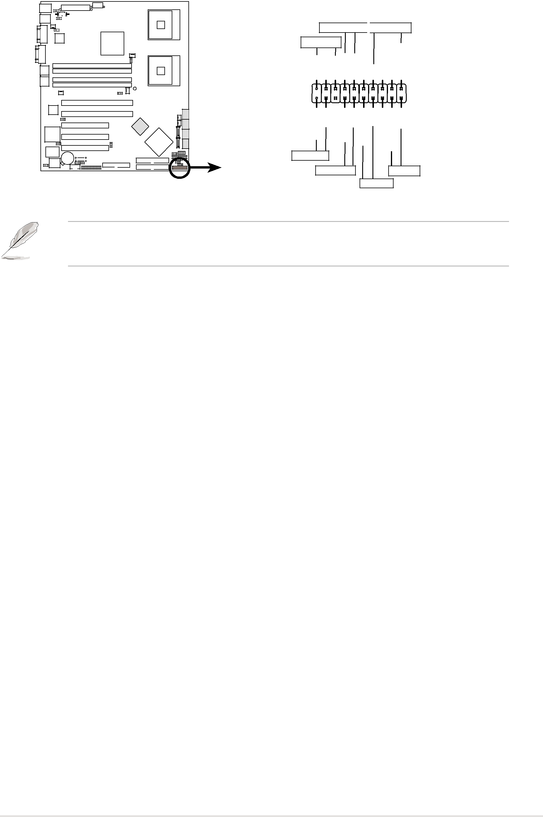
This connector supports several chassis-mounted functions.

Message LED Power LED

NCPLEDMLEDNC PLED+-MLED+-

SPEAKER

+5V GND GND SPKROUT

PANEL1


HDLED+ GND

NMIBTN# GND PWRBTN# GND NC

FP_RESET# GND


HDD LED


NCCH-DR

NMI Button

RESET

NCCH-DR System panel connector


PWRSW


The sytem panel connector is color-coded for easy connection. Refer to the connector descriptions on the next page for details.

System power LED (Green 3-pin PLED)

This 3-pin connector is for the system power LED. Connect the chassis power LED cable to this connector. The system power LED lights up when you turn on the system power, and blinks when the system is in sleep mode.

Message LED (Brown 2-pin MLED)

This connector is for the message LED cable that connects to the front panel message LED. The message LED indicates the booting status. The LED blinks when the system is in the boot process until the operating system is loaded.

System warning speaker (Orange 4-pin SPEAKER) This 4-pin connector is for the chassis-mounted system warning speaker. The speaker allows you to hear system beeps and warnings.

Hard disk drive activity LED (Red 2-pin HDD LED)

This 2-pin connector is for the HDD Activity LED. Connect the HDD Activity LED cable to this connector. The IDE LED lights up or flashes when data is read from or written to the HDD.

ATX power button/soft-off button (Yellow 2-pin PWRSW) This connector is for the system power button. Pressing the power button turns the system on or puts the system in sleep or soft-off mode depending on the BIOS settings. Pressing the power switch for more than four seconds while the system is ON turns the system OFF.

Reset button (Blue 2-pin RESET)

This 2-pin connector is for the chassis-mounted reset button for system reboot without turning off the system power.

ASUS NCCH-DR

2 - 35