11
!CAUTION
To reduce the risk of a laceration hazard, wear protective gloves when handling parts that have sharp edges.
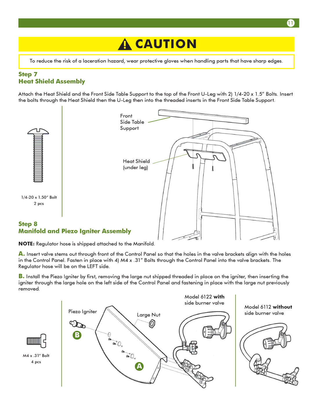
Step 7
Heat Shield Assembly
Attach the Heat Shield and the Front Side Table Support to the top of the Front
2 pcs
Front
Side Table
Support
Heat Shield ![]() (under leg)
(under leg)
Step 8
Manifold and Piezo Igniter Assembly
NOTE: Regulator hose is shipped attached to the Manifold.
A. Insert valve stems out through front of the Control Panel so that the holes in the valve brackets align with the holes in the Control Panel. Fasten in place with 4) M4 x .31” Bolts through the Control Panel into the valve brackets. The Regulator hose will be on the LEFT side.
B. Install the Piezo Igniter by first, removing the large nut shipped threaded in place on the igniter, then inserting the igniter through the large hole on the left side of the Control Panel and fastening in place with the large nut previously removed.
M4 x .31” Bolt
4 pcs
Model 6122 with side burner valve
Piezo Igniter | Large Nut |
|
B
A
Model 6112 without side burner valve