35
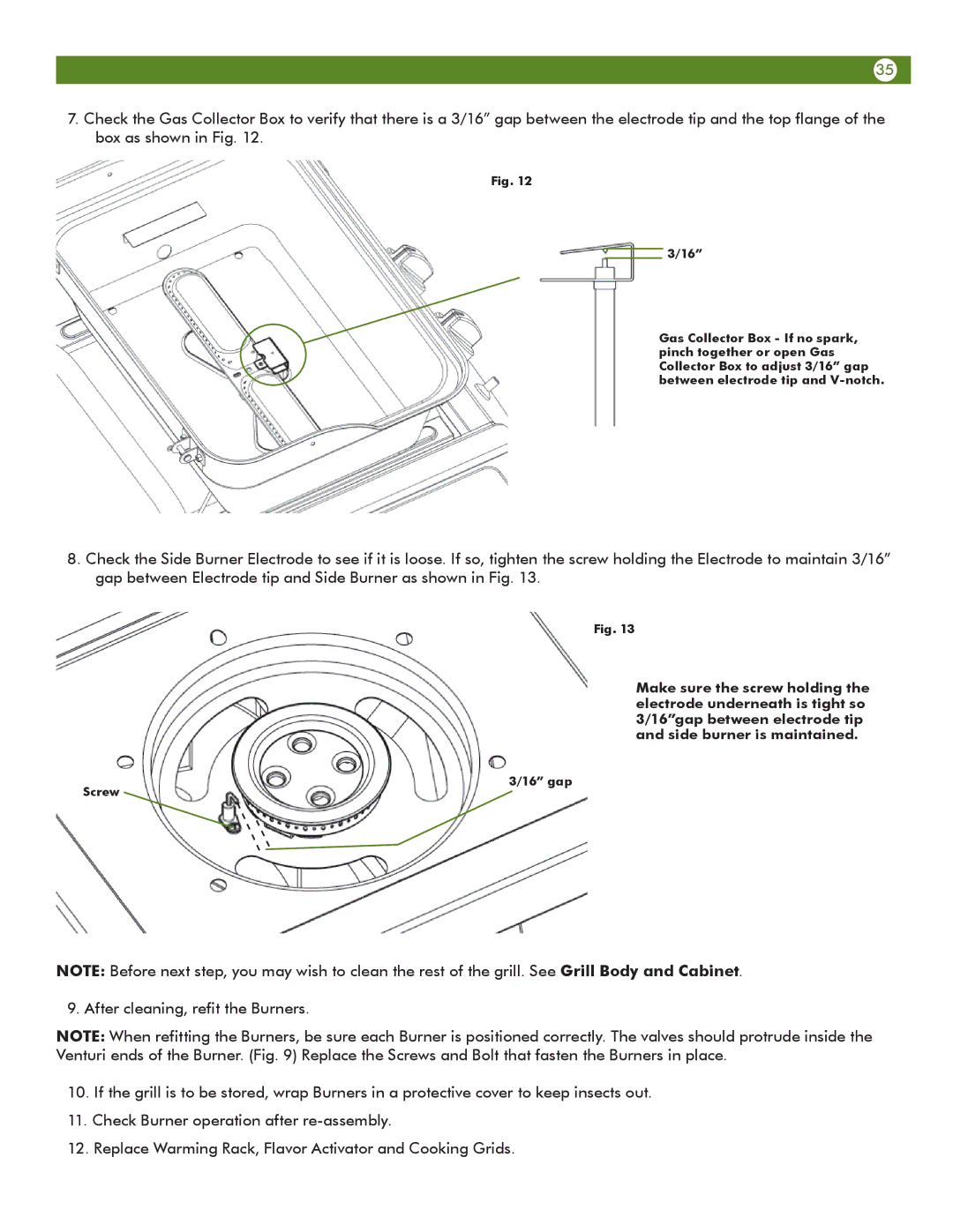
7.Check the Gas Collector Box to verify that there is a 3/16” gap between the electrode tip and the top flange of the box as shown in Fig. 12.
Fig. 12
3/16” gap
3/16”
Gas Collector Box - If no spark, pinch together or open Gas Collector Box to adjust 3/16” gap between electrode tip and
8.Check the Side Burner Electrode to see if it is loose. If so, tighten the screw holding the Electrode to maintain 3/16” gap between Electrode tip and Side Burner as shown in Fig. 13.
Screw
Fig. 13
Make sure the screw holding the electrode underneath is tight so 3/16”gap between electrode tip and side burner is maintained.
3/16” gap
NOTE: Before next step, you may wish to clean the rest of the grill. See Grill Body and Cabinet.
9. After cleaning, refit the Burners.
NOTE: When refitting the Burners, be sure each Burner is positioned correctly. The valves should protrude inside the Venturi ends of the Burner. (Fig. 9) Replace the Screws and Bolt that fasten the Burners in place.
10.If the grill is to be stored, wrap Burners in a protective cover to keep insects out.
11.Check Burner operation after
12.Replace Warming Rack, Flavor Activator and Cooking Grids.