9
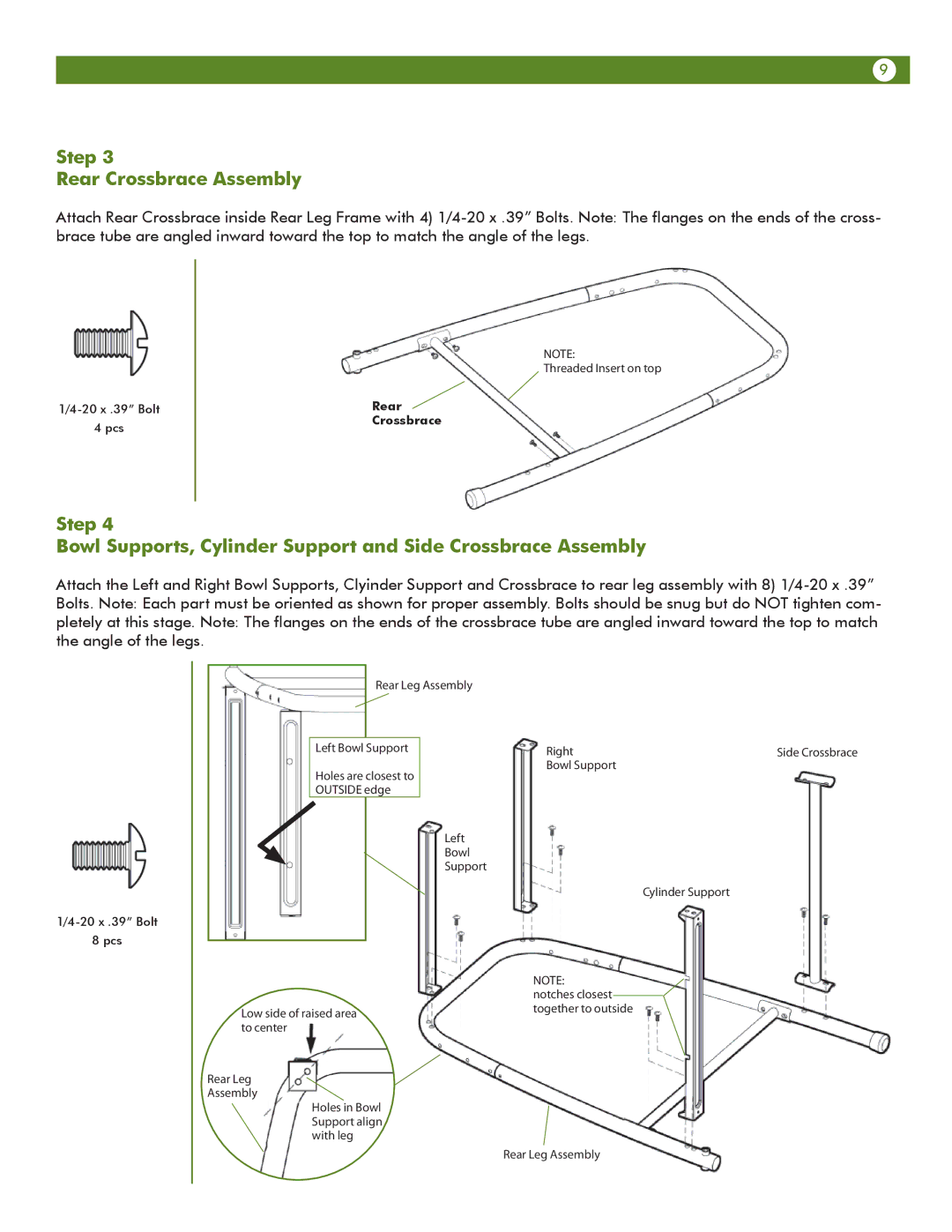
Step 3
Rear Crossbrace Assembly
Attach Rear Crossbrace inside Rear Leg Frame with 4)
4 pcs
NOTE:
Threaded Insert on top
Rear
Crossbrace
Step 4
Bowl Supports, Cylinder Support and Side Crossbrace Assembly
Attach the Left and Right Bowl Supports, Clyinder Support and Crossbrace to rear leg assembly with 8)
8 pcs
|
| Rear Leg Assembly |
|
| |
|
|
|
|
|
|
| Left Bowl Support |
| Right | Side Crossbrace | |
| Holes are closest to |
| Bowl Support |
| |
|
|
|
| ||
| OUTSIDE edge |
|
|
| |
Left
Bowl
Support
Cylinder Support
Low side of raised area to center
Rear Leg
Assembly
Holes in Bowl Support align with leg
NOTE:
notches closest together to outside
Rear Leg Assembly