14
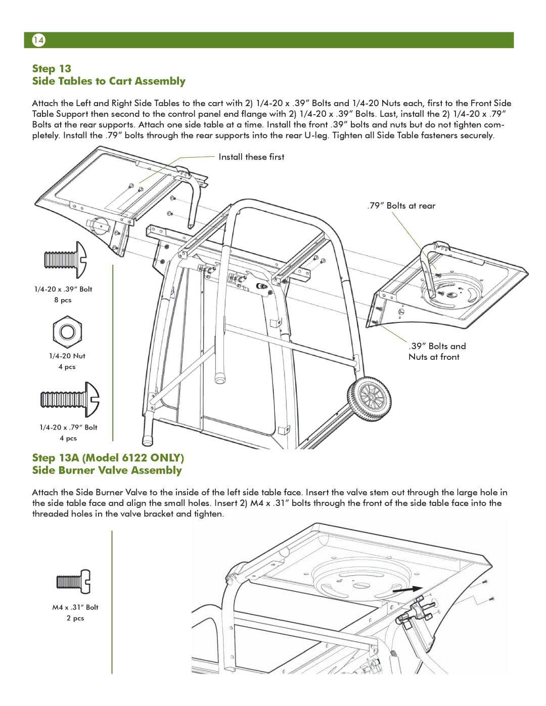
Step 13
Side Tables to Cart Assembly
Attach the Left and Right Side Tables to the cart with 2)
Install these first
.79” Bolts at rear
8 pcs
4 pcs
4 pcs
.39” Bolts and Nuts at front
Step 13A (Model 6122 ONLY)
Side Burner Valve Assembly
Attach the Side Burner Valve to the inside of the left side table face. Insert the valve stem out through the large hole in the side table face and align the small holes. Insert 2) M4 x .31” bolts through the front of the side table face into the threaded holes in the valve bracket and tighten.
M4 x .31” Bolt
2 pcs