PAGE 26 OPTIONAL EQUIPMENT
Stove Leg Installation (Brass # 99200500, Cast Black # 99200800, Black Steel # 99200100)
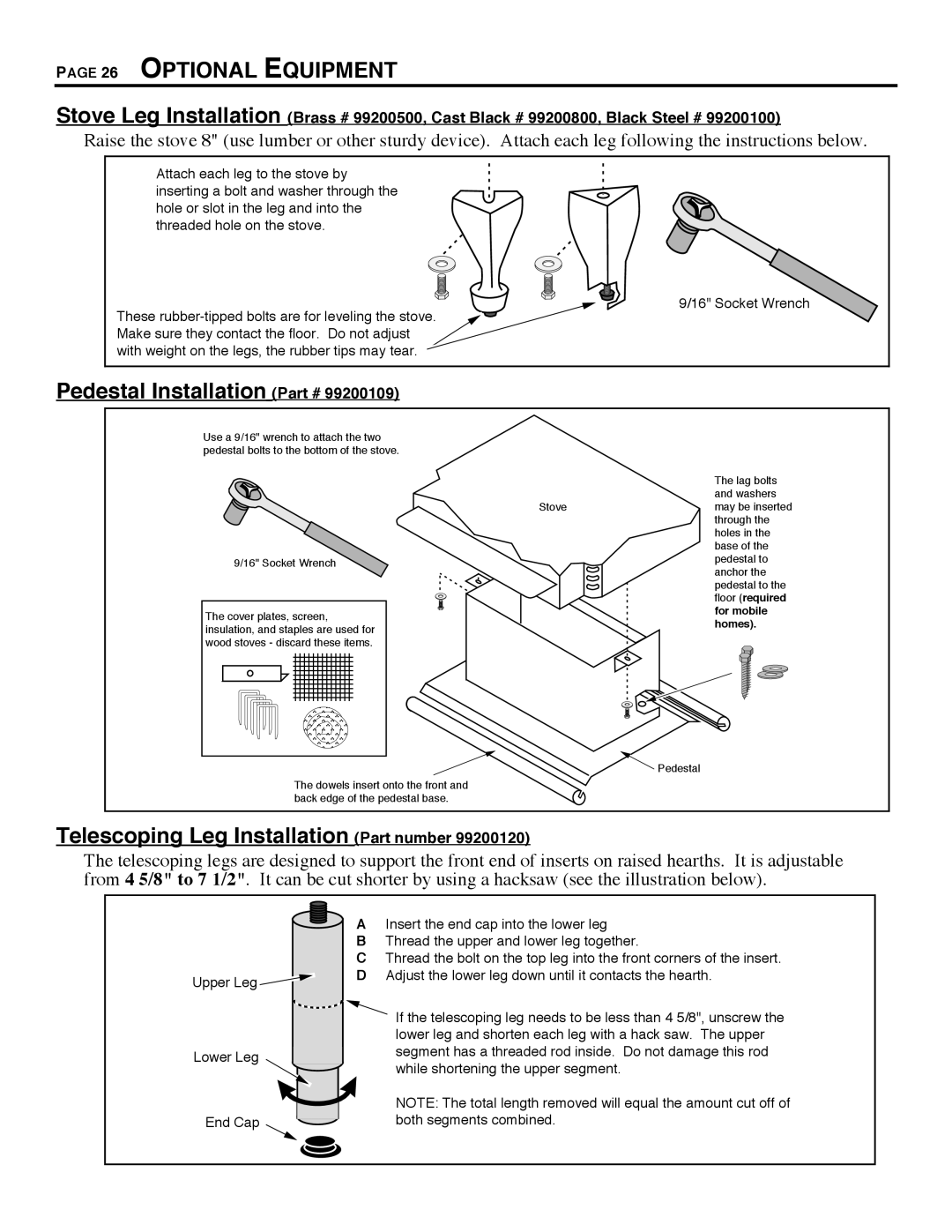
Raise the stove 8" (use lumber or other sturdy device). Attach each leg following the instructions below.
Attach each leg to the stove by inserting a bolt and washer through the hole or slot in the leg and into the threaded hole on the stove.
9/16" Socket Wrench
These
Pedestal Installation (Part # 99200109)
Use a 9/16" wrench to attach the two pedestal bolts to the bottom of the stove.
9/16" Socket Wrench
The cover plates, screen, insulation, and staples are used for wood stoves - discard these items.
The dowels insert onto the front and back edge of the pedestal base.
| The lag bolts |
| and washers |
Stove | may be inserted |
| through the |
| holes in the |
| base of the |
| pedestal to |
| anchor the |
| pedestal to the |
| floor (required |
| for mobile |
| homes). |
![]() Pedestal
Pedestal
Telescoping Leg Installation (Part number 99200120)
The telescoping legs are designed to support the front end of inserts on raised hearths. It is adjustable from 4 5/8" to 7 1/2". It can be cut shorter by using a hacksaw (see the illustration below).
Upper Leg |
Lower Leg |
End Cap |
AInsert the end cap into the lower leg
BThread the upper and lower leg together.
CThread the bolt on the top leg into the front corners of the insert. D Adjust the lower leg down until it contacts the hearth.
![]() If the telescoping leg needs to be less than 4 5/8", unscrew the lower leg and shorten each leg with a hack saw. The upper segment has a threaded rod inside. Do not damage this rod while shortening the upper segment.
If the telescoping leg needs to be less than 4 5/8", unscrew the lower leg and shorten each leg with a hack saw. The upper segment has a threaded rod inside. Do not damage this rod while shortening the upper segment.
NOTE: The total length removed will equal the amount cut off of both segments combined.
