AXIS Q1755/-E - Unit connectors
•Digital input - An alarm input for connecting devices that can toggle between an open and closed circuit, for exam- ple: PIRs, door/window contacts, glass break detectors, etc. When a signal is received the state changes and the input becomes active (shown under Events > Port Status.)
Notes:
•The I/O connector on AXIS
•For information on how to connect external devices, refer to the Installation Guide supplied with the product.
Function | Pin number | Notes | Specifications |
|
|
|
|
GND | 1 | Ground |
|
|
|
|
|
3.3V DC Power | 2 | Can be used to power auxiliary equipment. | Max load = 250mA |
|
| Note: |
|
|
| This pin can only be used as power out. |
|
|
|
|
|
Configurable | 3 - 4 | Digital input - Connect to GND to activate, or leave | Min input = - 40V DC |
(Input or Output) |
| floating (or unconnected) to deactivate. | Max input = + 40V DC |
|
| AXIS |
|
|
| delivery. |
|
|
|
|
|
|
| Digital output - Uses an | Max load = 100mA |
|
| with the source connected to GND. If used with an | Max voltage = + 40V DC |
|
| external relay, a diode must be connected in parallel |
|
|
| with the load, for protection against voltage tran- |
|
|
| sients. |
|
|
|
|
|
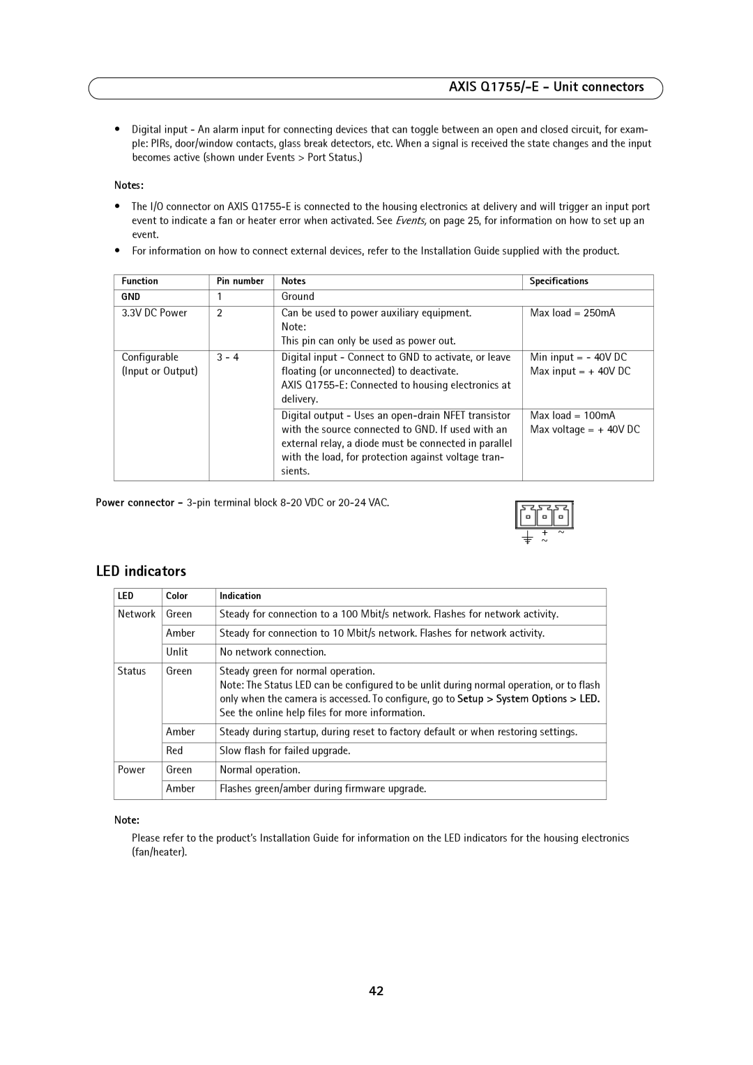
Power connector -
|
|
|
|
|
|
| + ~ | ||
|
|
|
| ||||||
LED indicators |
|
|
|
|
|
| ~ | ||
|
|
|
|
|
| ||||
|
|
|
|
|
|
| |||
|
|
|
|
|
|
|
|
|
|
| LED | Color | Indication | ||||||
|
|
|
|
|
|
|
|
|
|
| Network | Green | Steady for connection to a 100 Mbit/s network. Flashes for network activity. | ||||||
|
|
|
|
|
|
|
|
|
|
|
| Amber | Steady for connection to 10 Mbit/s network. Flashes for network activity. | ||||||
|
|
|
|
|
|
|
|
|
|
|
| Unlit | No network connection. | ||||||
|
|
|
|
|
|
|
|
|
|
| Status | Green | Steady green for normal operation. | ||||||
|
|
| Note: The Status LED can be configured to be unlit during normal operation, or to flash | ||||||
|
|
| only when the camera is accessed. To configure, go to Setup > System Options > LED. | ||||||
|
|
| See the online help files for more information. | ||||||
|
|
|
|
|
|
|
|
|
|
|
| Amber | Steady during startup, during reset to factory default or when restoring settings. | ||||||
|
|
|
|
|
|
|
|
|
|
|
| Red | Slow flash for failed upgrade. | ||||||
|
|
|
|
|
|
|
|
|
|
| Power | Green | Normal operation. | ||||||
|
|
|
|
|
|
|
|
|
|
|
| Amber | Flashes green/amber during firmware upgrade. | ||||||
|
|
|
|
|
|
|
|
|
|
Note:
Please refer to the product’s Installation Guide for information on the LED indicators for the housing electronics (fan/heater).
42