NEWDAT Bits 1and 0
Indicates if new data has been written into this slot by either the bus controller (receive messages) or the controller (transmit objects).
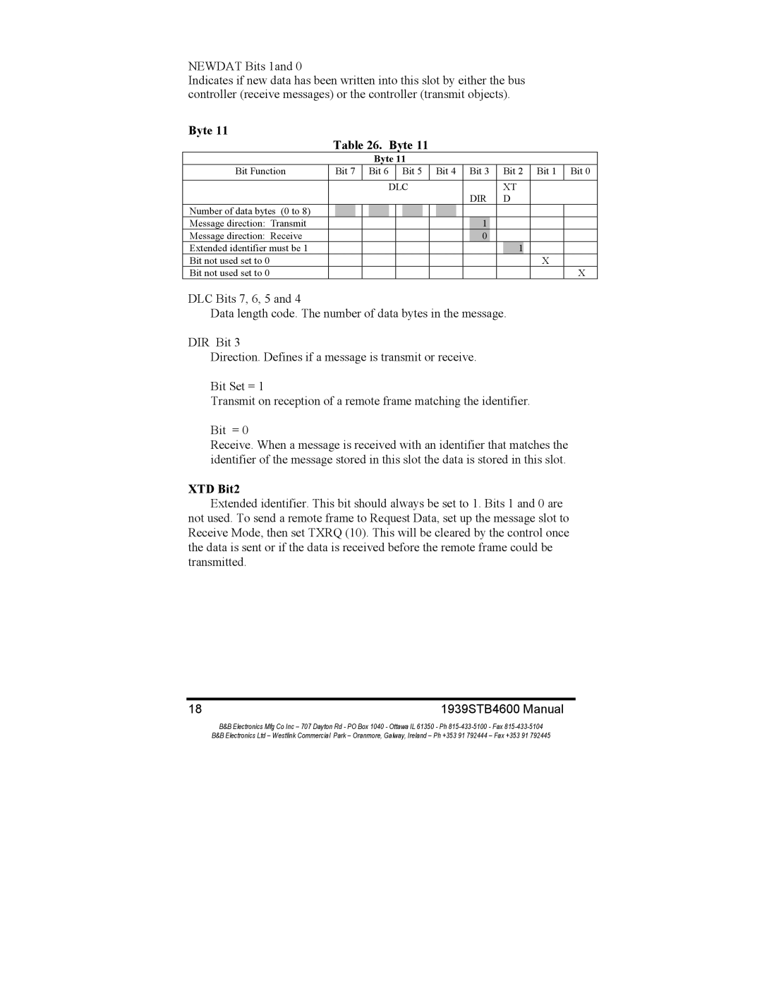
Byte 11
Table 26. Byte 11
Byte 11
Bit Function | Bit 7 | Bit 6 | Bit 5 | Bit 4 | Bit 3 |
| Bit 2 | Bit 1 | Bit 0 | |||||||||||
|
|
|
|
|
|
|
|
|
|
|
|
|
|
|
|
|
|
|
|
|
|
|
|
|
| DLC |
|
|
|
|
|
| XT |
| |||||||
|
|
|
|
|
|
|
|
|
|
|
|
| DIR |
| D |
| ||||
Number of data bytes (0 to 8) |
|
|
|
|
|
|
|
|
|
|
|
|
|
|
|
|
|
|
|
|
Message direction: Transmit |
|
|
|
|
|
|
|
|
|
|
|
|
| 1 |
|
|
|
|
|
|
Message direction: Receive |
|
|
|
|
|
|
|
|
|
|
|
|
| 0 |
|
|
|
|
|
|
Extended identifier must be 1 |
|
|
|
|
|
|
|
|
|
|
|
|
|
|
|
| 1 |
|
|
|
Bit not used set to 0 |
|
|
|
|
|
|
|
|
|
|
|
|
|
|
|
|
|
| X |
|
Bit not used set to 0 |
|
|
|
|
|
|
|
|
|
|
|
|
|
|
|
|
|
|
| X |
DLC Bits 7, 6, 5 and 4
Data length code. The number of data bytes in the message.
DIR Bit 3
Direction. Defines if a message is transmit or receive.
Bit Set = 1
Transmit on reception of a remote frame matching the identifier.
Bit = 0
Receive. When a message is received with an identifier that matches the identifier of the message stored in this slot the data is stored in this slot.
XTD Bit2
Extended identifier. This bit should always be set to 1. Bits 1 and 0 are not used. To send a remote frame to Request Data, set up the message slot to Receive Mode, then set TXRQ (10). This will be cleared by the control once the data is sent or if the data is received before the remote frame could be transmitted.
18 | 1939STB4600 Manual | |
| B&B Electronics Mfg Co Inc – 707 Dayton Rd - PO Box 1040 - Ottawa IL 61350 - Ph | - Fax |
| B&B Electronics Ltd – Westlink Commercial Park – Oranmore, Galway, Ireland – Ph +353 91 792444 | – Fax +353 91 792445 |
