SAE-J1939 Control Header
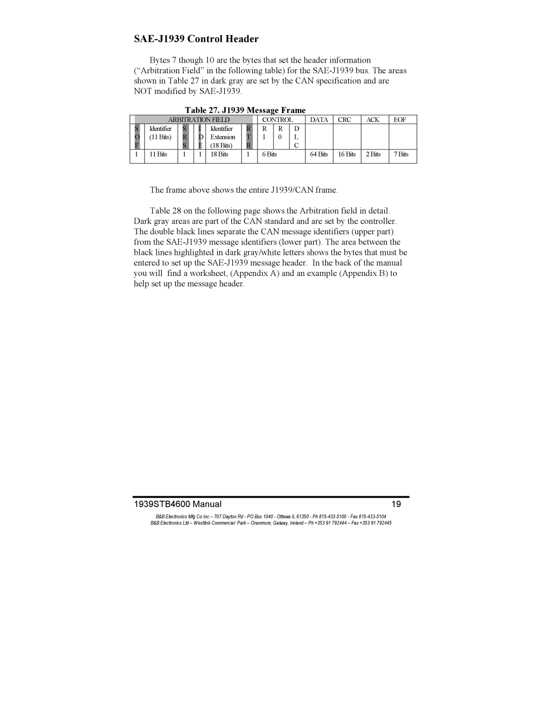
Bytes 7 though 10 are the bytes that set the header information (“Arbitration Field” in the following table) for the
Table 27. J1939 Message Frame
|
|
| ARBITRATION FIELD |
|
|
| CONTROL |
| DATA | CRC | ACK | EOF | ||||||||
| S |
| Identifier |
| S |
| I | Identifier |
| R |
| R |
| R |
| D |
|
|
|
|
| O |
| (11 Bits) |
| R |
| D | Extension |
| T |
| 1 |
| 0 |
| L |
|
|
|
|
| F |
|
|
| S |
| E | (18 Bits) |
| R |
|
|
|
|
| C |
|
|
|
|
| 1 |
| 11 Bits |
| 1 |
| 1 | 18 Bits |
| 1 |
| 6 Bits |
|
|
| 64 Bits | 16 Bits | 2 Bits | 7 Bits | |
|
|
|
|
|
|
|
|
|
|
|
|
|
|
|
|
|
|
|
|
|
The frame above shows the entire J1939/CAN frame.
Table 28 on the following page shows the Arbitration field in detail. Dark gray areas are part of the CAN standard and are set by the controller. The double black lines separate the CAN message identifiers (upper part) from the
1939STB4600 Manual | 19 |
B&B Electronics Mfg Co Inc – 707 Dayton Rd - PO Box 1040 - Ottawa IL 61350 - Ph
B&B Electronics Ltd – Westlink Commercial Park – Oranmore, Galway, Ireland – Ph +353 91 792444 – Fax +353 91 792445
