Chapter 3 - Commands
There are only two commands required to control the 232SDD16: set output lines, and read I/O lines. Three additional commands are used for configuring the module: define I/O lines, set
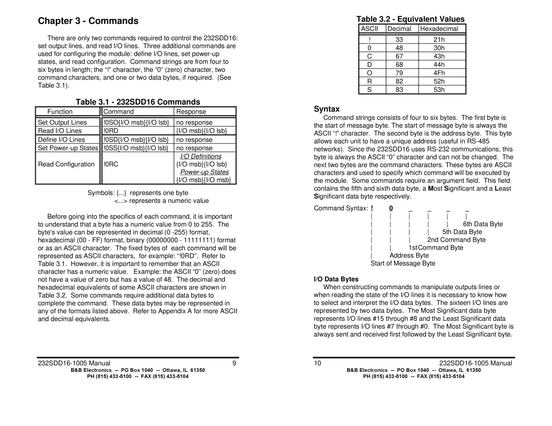
Table 3.1 - 232SDD16 Commands
Function |
| Command | Response |
|
|
|
|
Set Output Lines |
| !0SO{I/O msb}{I/O lsb} | no response |
Read I/O Lines |
| !0RD | {I/O msb}{I/O lsb} |
Define I/O Lines |
| !0SD{I/O msb}{I/O lsb} | no response |
Set |
| !0SS{I/O msb}{I/O lsb} | no response |
|
|
| I/O Definitions |
Read Configuration |
| !0RC | {I/O msb}{I/O lsb} |
|
|
|
|
|
|
| {I/O msb}{I/O msb} |
Symbols: {...} represents one byte | |||
|
| <...> represents a numeric value | |
Before going into the specifics of each command, it is important to understand that a byte has a numeric value from 0 to 255. The byte's value can be represented in decimal (0
9 |
Table 3.2 - Equivalent Values
ASCII | Decimal | Hexadecimal |
|
|
|
! | 33 | 21h |
0 | 48 | 30h |
C | 67 | 43h |
D | 68 | 44h |
O | 79 | 4Fh |
R | 82 | 52h |
S | 83 | 53h |
Syntax
Command strings consists of four to six bytes. The first byte is the start of message byte. The start of message byte is always the ASCII “!” character. The second byte is the address byte. This byte allows each unit to have a unique address (useful in
Command Syntax: ! | 0 | _ | _ | _ | _ |
6th Data Byte | |||||
5th Data Byte | |||||
2nd Command Byte | |||||
1stCommand Byte | |||||
Address Byte |
|
| |||
Start of Message Byte
I/O Data Bytes
When constructing commands to manipulate outputs lines or when reading the state of the I/O lines it is necessary to know how to select and interpret the I/O data bytes. The sixteen I/O lines are represented by two data bytes. The Most Significant data byte represents I/O lines #15 through #8 and the Least Significant data byte represents I/O lines #7 through #0. The Most Significant byte is always sent and received first followed by the Least Significant byte.
10 |
B&B Electronics | B&B Electronics |
PH (815) | PH (815) |