Hardware Overview
Ethernet Port Connector
The Ethernet Port connector is a standard
On the PES1A/ PESV1A two indicator LEDs are built into the
Serial Port Connector
The Serial Port Connector is a
Refer to Appendices D, E and F for connection
Power Connector
Power is supplied to the PES1A/PESV1A by PoE (Power over Ethernet) via the
Refer to Appendix E for Ethernet connection
Output Power Connector (PESV1A only)
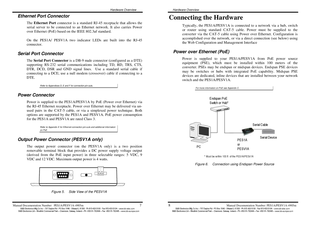
The output power connector (on the PESV1A only) is a two position removable terminal block that provides a DC power supply voltage output (derived from the PoE input power) in three selectable ranges: 5 VDC, 9 VDC and 12 VDC. Maximum output power is 4 watts.
Figure 5. Side View of the PESV1A
Manual Documentation Number: | 7 |
Hardware Overview
Connecting the Hardware
Typically, the PES1A/PESV1A is connected to a network via a hub, switch or router using standard
Power over Ethernet (PoE)
Power is supplied to your PES1A/PESV1A from PoE power source equipment (PSE), which must be installed within 100 meters of the converter. PSEs may be endspan or midspan devices. Endspan PSE devices may be switches or hubs with integrated PoE capability. Midspan PSE devices are dedicated, inline devices that are installed between your network switch and the PES1A/PESV1A.
For more information on PoE see Appendix C.
Endspan PoE
Switch or Hub*
|
| Serial Cable |
| PES1A | Serial Device |
|
| |
PC | or |
|
PESV1A |
| |
|
|
* Must be w ithin 100 ft of the PES1A/PESV1A
Figure 6. Connection using Endspan Power Source
8 | Manual Documentation Number: |
B&B Electronics Mfg Co Inc – 707 Dayton Rd - PO Box 1040 - Ottawa IL 61350 - Ph | B&B Electronics Mfg Co Inc – 707 Dayton Rd - PO Box 1040 - Ottawa IL 61350 - Ph |
B&B Electronics Ltd – Westlink Commercial Park – Oranmore, Galway, Ireland – Ph +353 | B&B Electronics Ltd – Westlink Commercial Park – Oranmore, Galway, Ireland – Ph +353 |
