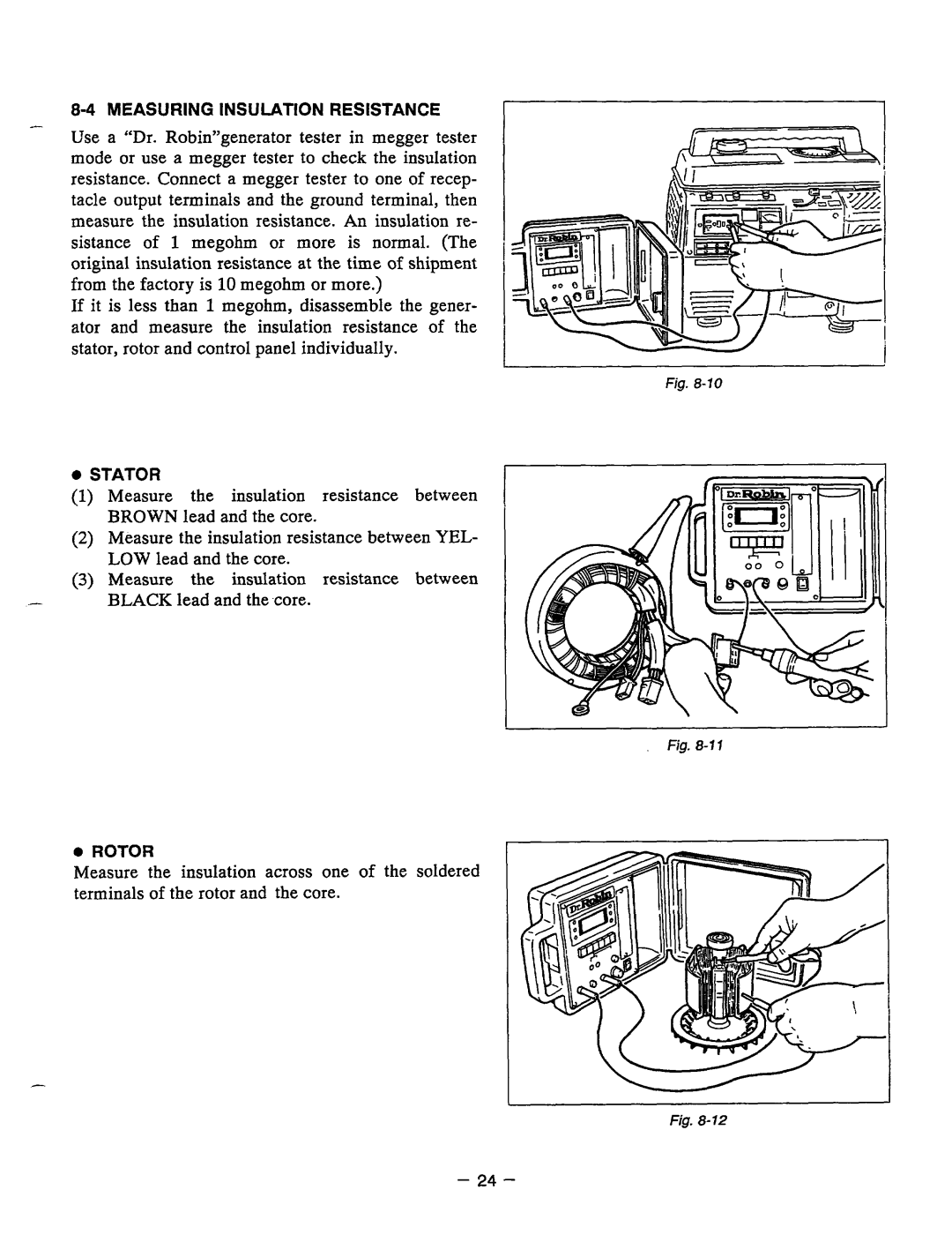
8-4 MEASURING INSULATION RESISTANCE
Use a “Dr. Robin”generator tester in megger tester mode or use a megger tester to check the insulation resistance. Connect a megger tester to one of recep- tacle output terminals and the ground terminal, then measure the insulation resistance. An insulation re- sistance of 1 megohm or more is normal. (The original insulation resistance at the time of shipment from the factory is 10 megohm or more.)
If it is lessthan 1 megohm, disassemble the gener- ator andmeasure the insulation resistance of the stator, rotor and control panel individually.
0STATOR
(1) Measurethe insulation resistance between BROWN lead and the core.
(2)Measure the insulation resistance between YEL- LOW lead and the core.
(3)Measure the insulation resistance between
-BLACK leadand the core.
0ROTOR
Measure the insulation acrossone of the soldered terminals of the rotor and the core.
fig.
I
IJ
Fig.
Fig.
- 24 -