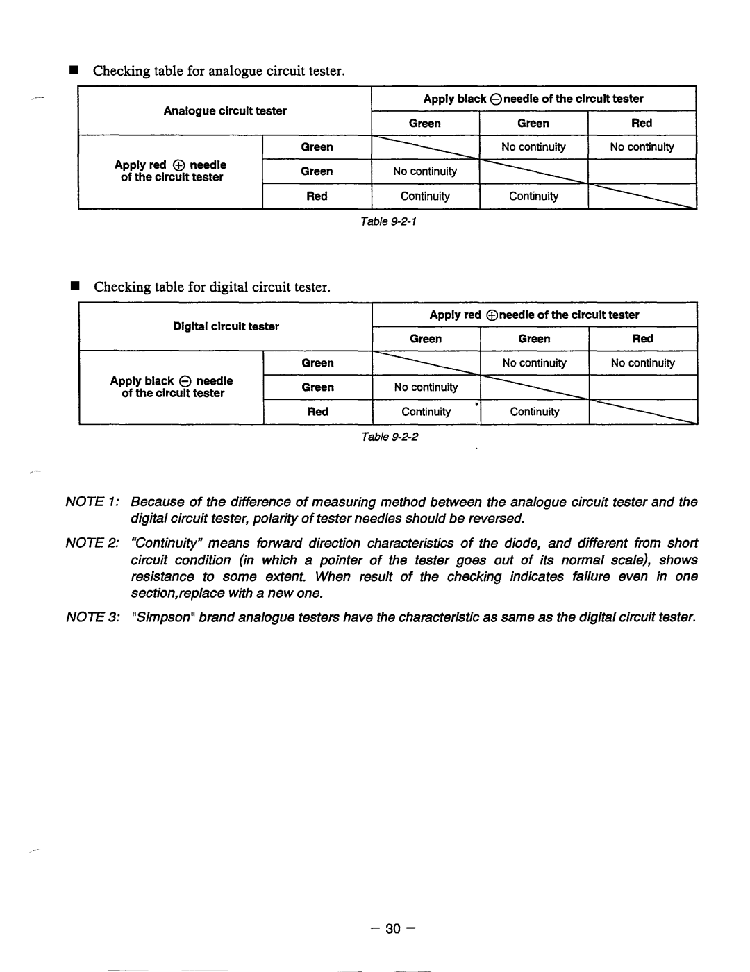
Checkingtableforanaloguecircuittester.
~~~ | ~~ | ~~~~ | ~~~ | ~~~ | ~~~ |
| |
Analogue | clrcult | tester | Apply blackOneedle of the clrcult tester | ||||
Green | Green | Red | |||||
|
|
|
| ||||
|
|
| Green |
|
| No continuity | |
Applyred @ needle | Green |
|
|
| |||
of the clrcult | tester |
|
|
| |||
|
|
|
| ||||
Red
Checkingtablefordigitalcircuittester.
Digital clrcult | tester | Apply red @needleof the clrcult tester |
| ||
Red | Green | Green |
Apply black 0 needle | Green | No continuity |
Green |
| |
of the clrcult tester |
| |
|
| |
| Red |
|
|
|
_-
NOTE 1: Because of the difference of measuring method between the analogue circuit tester and the digital circuit tester, polarityof tester needles shouldbe reversed,
NOTE 2: “Continuity”meansforwarddirectioncharacteristics of the diode,anddifferentfromshort circuit condition (in which a pointer of thetestergoes out of its normal scale),shows
resistance to some extent.Whenresult of thecheckingindicates failure eveninone section,replace with a new one.
NOTE 3: “Simpson“ brand analogue testers have the characteristicas same as the digital circuit tester.
L
- 30 -