9.CHECKINGFUNCTIONALMEMBERS
Fig.
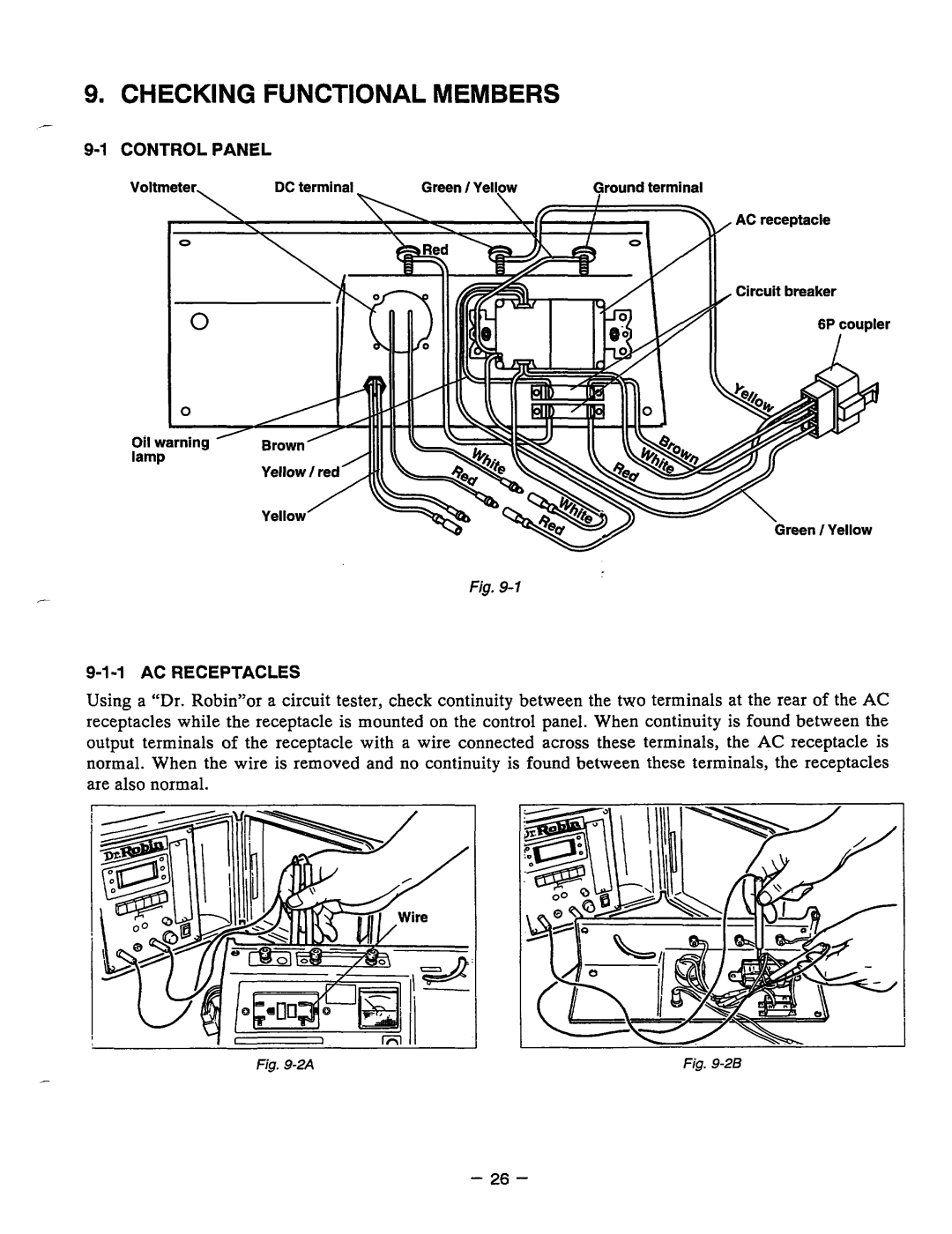
Using a “Dr. Robin”or a circuit tester, check continuity between the two terminals at the rear of the AC receptacles while the receptacle is mounted on the control panel. When continuity is found between the output terminals of thereceptaclewith a wire connected acrossthese terminals, theACreceptacle is normal. When the wire is removed and no continuity is found between these terminals, the receptacles are alsonormal.
- | Fig. | Fig. |
|
|
- 26 -