-
.
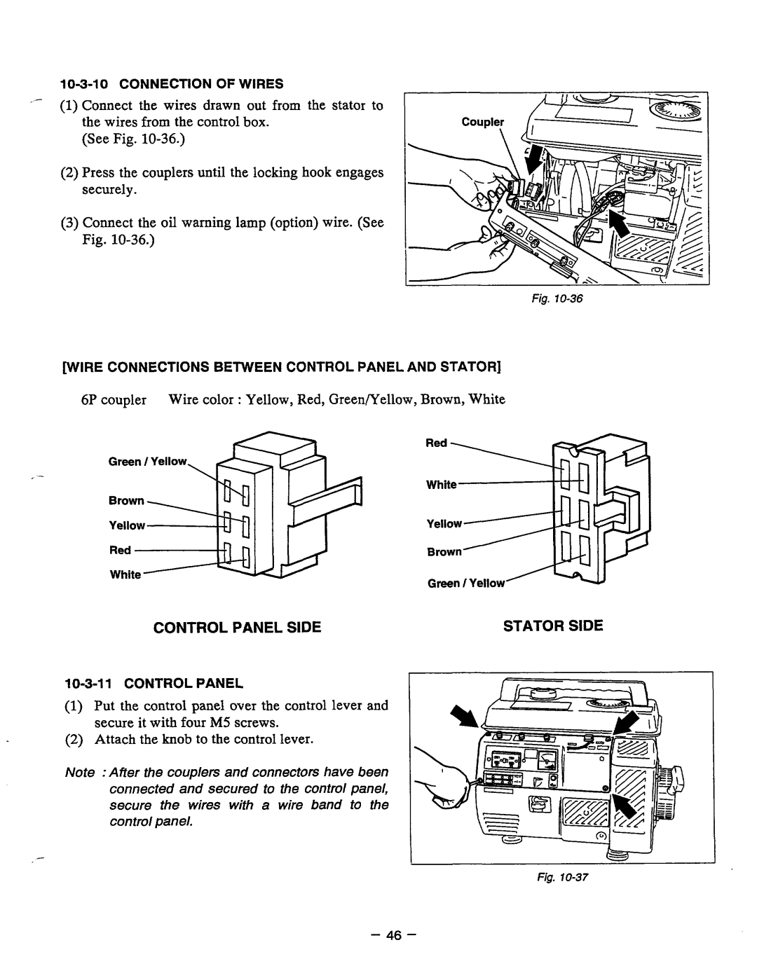
(1)Connectthewiresdrawnout from thestatorto the wiresfrom the controlbox.
(See Fig.
(2)Press the couplers untilthe locking hook engages securely.
(3)Connect the oil warning lamp (option) wire. (See Fig.
\
fig.
[WIRE CONNECTIONS BETWEEN CONTROL PANEL AND STATOR]
6P couplerWirecolor :Yellow, Red, GreenrYellow, Brown, White
Green / Yellow
CONTROL PANEL SIDE
(1)Putthecontrolpanelover the control lever and secure it with fourM5 screws.
(2)Attach the knob to the control lever.
Note :After the couplers and connectors have been
connected and secured to the control panel,
secure the wireswithawireband to the controlpanel.
Green / Yellow
STATOR SIDE
c
Fig.
- 46 -