-
Hz
|
|
| (RxlR +lo%) |
Specification | AC Windlng | DC Windlng | Condenser Winging |
Voltage | Brown I White | Green I Green | Black / Black |
60 | 120v | 1.4 Q | 0.62 Q | 4.8 R |
Table
NOTE: If the circuit tester is not sufficiently accurate$ may not show the values given and may give erroneous readings.
Erroneous reading will also occur whenthereisa wide variationofresistanceamong coil
windings or whenmeasurement is performed at ambienttemperaturesdifferentfrom
ZO"C(68"F).
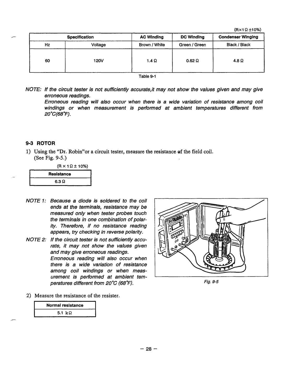
1)Using the "Dr. Robin"or a circuit tester, measurethe resistance ef the field coil. (See Fig.
-
(RxlR+10%)
Resistance
NOTE I: Becausea diode issolderedto the coil ends at the terminals, resistance may be measured only when tester probes touch the terminals in one combination of polar- ity.Therefore, if noresistancereading appears, trychecking in reverse polarity.
NOTE 2: If the circuit tester is not sufficiently accu-
rate, it may not show the valuesgiven |
| ||
and maygive erroneous readings. |
| ||
Erroneousreading will also occur when |
| ||
thereisa | wide variation | of resistance |
|
among coil windingsor | when meas- |
| |
urement is performed at ambient tem- | Fig. | ||
peratures | different from20°C (68°F). | ||
2)Measure the resistance of the resister.
_-
- 28 -