-5-3-3 DC OUTPUT
DC output is taken out from the DC coil and is fed to the diode stack (rectifier) where the output undergoes
thedirection @, but doesnotallowthecurrent to flow in the direction8, as shown in Fig.
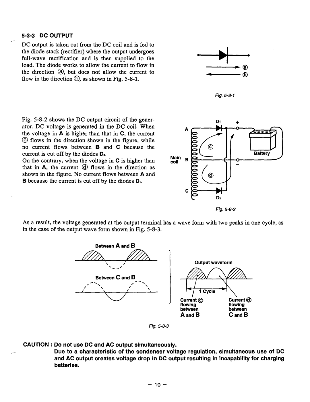
Fig. 5-8-2 shows the DC output circuit of the gener- ator. DC voltage is generated in the DC coil. When the voltage in A is higher than that in Cythe current
@flows in the direction shown in the figure, while
nocurrentflows between B and C becausethe current is cut off by the diodesD,.
On the contrary, when the voltage in C is higher than that in A, the current @ flows in thedirection as shown in the figure.No current flows betweenA and B because the current is cutoff by the diodes D,.
Main coil
4
- 0
Fig.
Dl +
Fig.
As a result, the voltage generated at the output terminalhas a wave form with two peaks in one cycle, as in the caseof the output wave form shownin Fig.
| Between A and 6 | 1 |
|
| |
| \ ' " 0 | / | Output waveform | ||
|
|
| |||
0 |
|
|
|
| |
/ | Between c and B | '\ |
|
| |
\ | / |
|
| ||
|
| / - |
|
|
|
I | \ | I | \ |
|
|
|
|
| |||
|
|
| j Curre'nt 0 |
| |
|
|
|
| flowing | flowing |
|
|
|
| between | between |
|
|
|
| A and B | C and B |
Fig.
CAUTION :Do not use DCand AC output simultaneously.
- Due to a characteristic of the condenservoltageregulation,simultaneous use ofDC and AC output creates voltage drop In DC output resultingin incapability for charging batterles.
- 10 -