PRINCIPLES OF OPERATION
PMG (optional) | Rotating Assembly |
PMG Field | Exciter Field | Exciter Armature | Main Field | Main Armature | L1 |
(rotor) | (stator) | (rotor) | (rotor) | (stator) | |
N | (+) |
|
|
|
|
|
| (+) |
|
| |
| DC |
| DC |
| L2 |
S | (in) |
| (in) |
|
|
|
|
|
|
| |
|
|
|
| ||
|
|
|
| L3 | |
PMG |
| 3 Phase AC (out) |
| 3 Phase AC (out) | |
|
|
|
|
| |
Armature |
|
|
|
|
|
(stator) |
|
| Rotating Rectifier Assembly |
|
|
|
|
| 3 Phase |
|
|
| Exciter Field Power |
| Input Power | |
| (DC out) |
| (shunt powered regulator) | |
Automatic | ||||
PMG Input Power (optional) |
| |||
Voltage |
| |||
(1 phase, 300/250 hertz) | Regulator |
| ||
|
|
| Sensing Input | |
|
|
| ||
|
|
| 3 phase (optional) | |
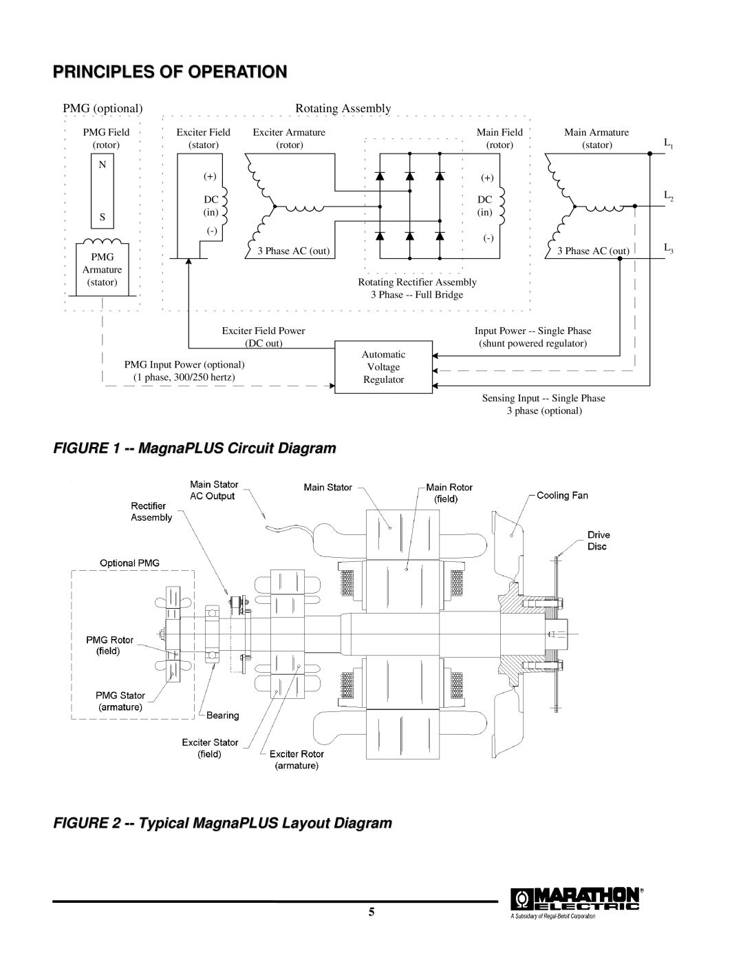
FIGURE 1 -- MagnaPLUS Circuit Diagram
FIGURE 2 -- Typical MagnaPLUS Layout Diagram
5