SWITCHABLE
ELECTRICAL CONNECTION INFORMATION
WARNING: High voltage may be present at receptacles and load studs while engine is operating – DANGER of electrical shock is present. Use extreme care.
LOAD RECEPTACLES
1.Voltage is present in 120/240 volt switch position only.
2.Load wires may be brought into receptacle compartment through access door at control station.
HARD WIRE LOAD TERMINAL BLOCK
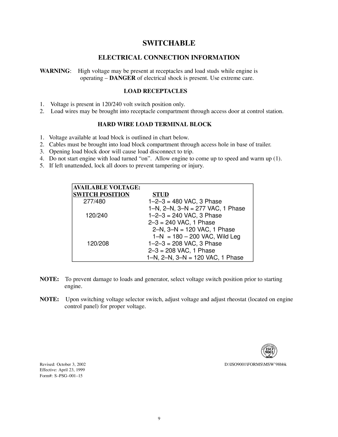
1.Voltage available at load block is outlined in chart below.
2.Cables must be brought into load block compartment through access hole in base of trailer.
3.Opening load block door will cause load disconnect to trip.
4.Do not start engine with load turned “on”. Allow engine to come up to speed and warm up (1).
5.If left unattended, lock all doors to prevent tampering or injury.
AVAILABLE VOLTAGE: |
|
SWITCH POSITION | STUD |
277/480 | |
| |
120/240 | |
| |
| |
| |
120/208 | |
| |
| |
|
|
NOTE: To prevent damage to loads and generator, select voltage switch position prior to starting engine.
NOTE: Upon switching voltage selector switch, adjust voltage and adjust rheostat (located on engine control panel) for proper voltage.
Revised: October 3, 2002 | D:\ISO9001\FORMS\MSW’98bbk |
Effective: April 23, 1999 |
|
Form#: |
|
9