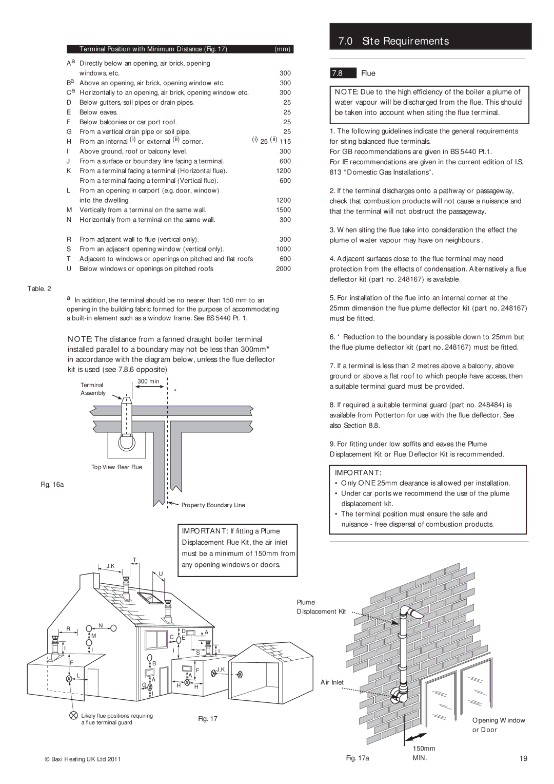
Terminal Position with Minimum Distance (Fig. 17)

(mm)

Aa

Directly below an opening, air brick, opening


Ba

windows, etc.

300

Above an opening, air brick, opening window etc.

300

Ca

Horizontally to an opening, air brick, opening window etc.

300

D

Below gutters, soil pipes or drain pipes.

25

E

Below eaves.

25

F

Below balconies or car port roof.

25

G

From a vertical drain pipe or soil pipe.

25

H

From an internal (i) or external (ii) corner.

(i) 25 (ii) 115

I

Above ground, roof or balcony level.

300

J

From a surface or boundary line facing a terminal.

600

K

From a terminal facing a terminal (Horizontal flue).

1200


From a terminal facing a terminal (Vertical flue).

600

L

From an opening in carport (e.g. door, window)


into the dwelling.

1200

M

Vertically from a terminal on the same wall.

1500

N

Horizontally from a terminal on the same wall.

300

7.0Site Requirements

7.8Flue

NOTE: Due to the high efficiency of the boiler a plume of water vapour will be discharged from the flue. This should be taken into account when siting the flue terminal.

1.The following guidelines indicate the general requirements for siting balanced flue terminals.

For GB recommendations are given in BS 5440 Pt.1.

For IE recommendations are given in the current edition of I.S.

813“Domestic Gas Installations”.

2.If the terminal discharges onto a pathway or passageway, check that combustion products will not cause a nuisance and that the terminal will not obstruct the passageway.


3. When siting the flue take into consideration the effect the

R

From adjacent wall to flue (vertical only).

300


plume of water vapour may have on neighbours .

S

From an adjacent opening window (vertical only).

1000


T

Adjacent to windows or openings on pitched and flat roofs

600


4. Adjacent surfaces close to the flue terminal may need

U

Below windows or openings on pitched roofs

2000


protection from the effects of condensation. Alternatively a flue


deflector kit (part no. 248167) is available.

Table. 2


a

In addition, the terminal should be no nearer than 150 mm to an


5. For installation of the flue into an internal corner at the

opening in the building fabric formed for the purpose of accommodating


25mm dimension the flue plume deflector kit (part no. 248167)

a built-in element such as a window frame. See BS 5440 Pt. 1.


must be fitted.

NOTE: The distance from a fanned draught boiler terminal


6. * Reduction to the boundary is possible down to 25mm but

installed parallel to a boundary may not be less than 300mm*


the flue plume deflector kit (part no. 248167) must be fitted.

in accordance with the diagram below, unless the flue deflector


7. If a terminal is less than 2 metres above a balcony, above

kit is used (see 7.8.6 opposite)


ground or above a flat roof to which people have access, then


300 min


Terminal


*


a suitable terminal guard must be provided.


Assembly


8. If required a suitable terminal guard (part no. 248484) is


available from Potterton for use with the flue deflector. See


also Section 8.8.


9. For fitting under low soffits and eaves the Plume


Displacement Kit or Flue Deflector Kit is recommended.


Top View Rear Flue


IMPORTANT:


Fig. 16a


• Only ONE 25mm clearance is allowed per installation.


• Under car ports we recommend the use of the plume


Property Boundary Line


displacement kit.


• The terminal position must ensure the safe and


nuisance - free dispersal of combustion products.


IMPORTANT: If fitting a Plume


Displacement Flue Kit, the air inlet


T


must be a minimum of 150mm from


J,K


any opening windows or doors.


U


Plume


Displacement Kit

R N

M

I I

F B

L

A

G

I

Likely flue positions requiring a flue terminal guard

© Baxi Heating UK Ltd 2011

C

D

A

E


I

S

I


F

J,K


A


H

H


Fig. 17

Air Inlet


150mm

Fig. 17a

MIN.

Opening Window or Door

19

Page 19
Image 19
Baxi Potterton Gold FSB 30 HE manual Flue, Min

Gold FSB 30 HE specifications

The Baxi Potterton Gold FSB 30 HE is a high-efficiency system boiler designed to meet the demands of modern homes while providing exceptional performance and reliability. As part of the Baxi Potterton Gold range, this model combines advanced engineering with user-friendly features, making it a top choice for homeowners and installers alike.

One of the primary features of the Baxi Potterton Gold FSB 30 HE is its impressive efficiency rating. With an ErP rating of A for heat and a seasonal efficiency of up to 90%, this boiler not only reduces energy consumption but also helps in lowering utility bills. The high-efficiency design ensures that more of the fuel consumed is converted into usable heat, making it an environmentally friendly option.

The boiler utilizes a lightweight design, weighing in at just 30 kg, which makes it easy to transport and install. Its compact size allows for flexibility in siting, meaning it can fit comfortably in kitchen cupboards or utility rooms without taking up excessive space. The small footprint caters to property owners looking to save on installation areas while still having a powerful heating system.

In terms of technology, the Baxi Potterton Gold FSB 30 HE features an integral thermostat and a user-friendly LCD display for easy boiler operation and maintenance. This advanced control system provides homeowners with accurate temperature readings and the ability to adjust settings with ease. The built-in diagnostics feature simplifies fault-finding and allows for quick resolutions, minimizing downtime.

The boiler is also equipped with weather compensation technology, which adjusts the heating output based on the external temperature. This ensures optimal performance year-round, maintaining a comfortable environment inside the home and optimizing energy use.

Safety features are paramount in the design of the Baxi Potterton Gold FSB 30 HE. It includes a range of built-in safeguards, such as a frost protection mode and an overheat thermostat, giving users peace of mind. Moreover, it is compatible with various heating controls and can be linked to smart home systems, offering further convenience and energy-saving options.

Overall, the Baxi Potterton Gold FSB 30 HE stands out for its efficiency, compact design, and advanced technology, making it a reliable solution for domestic heating needs. With a solid reputation for quality and performance, the Gold FSB 30 HE continues to be a favored choice for those looking to invest in an effective system boiler.