Installation
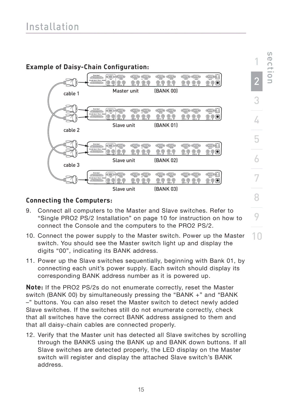
Example of Daisy-Chain Configuration:
Slave Input
Master Input /Slave Output | ��� | ����� | ����� | �� ��� �� | ����� | ����� | ����� | ��� �� | ����� |
|
|
|
|
|
|
|
|
| |
|
| �� | �� | �� | �� | �� | �� | �� | �� |
cable 1 |
| Master unit |
| (BANK 00) |
|
|
| ||
|
|
|
|
|
|
|
|
| |
Slave Input |
|
|
|
|
|
|
|
|
|
Master Input /Slave Output | ��� | ����� | ����� | �� ��� �� | ����� | ����� | ����� | ��� �� | ����� |
|
|
|
|
|
|
|
|
| |
|
| �� | �� | �� | �� | �� | �� | �� | �� |
cable 2 |
| Slave unit |
| (BANK 01) |
|
|
| ||
|
|
|
|
|
|
|
|
| |
Slave Input |
|
|
|
|
|
|
|
|
|
Master Input /Slave Output | ��� | ����� | ����� | �� ��� �� | ����� | ����� | ����� | ��� �� | ����� |
|
|
|
|
|
|
|
|
| |
|
| �� | �� | �� | �� | �� | �� | �� | �� |
cable 3 |
| Slave unit |
| (BANK 02) |
|
|
| ||
|
|
|
|
|
|
|
|
| |
Slave Input |
|
|
|
|
|
|
|
|
|
Master Input /Slave Output | ��� | ����� | ����� | �� ��� �� | ����� | ����� | ����� | ��� �� | ����� |
|
| �� | �� | �� | �� | �� | �� | �� | �� |
|
| Slave unit |
| (BANK 03) |
|
|
| ||
Connecting the Computers:
9.Connect all computers to the Master and Slave switches. Refer to “Single PRO2 PS/2 Installation” on page 10 for instruction on how to connect the Console and the computers to the PRO2 PS/2.
10.Connect the power supply to the Master switch. Power up the Master switch. You should see the Master switch light up and display the digits “00”, indicating its BANK address.
11.Power up the Slave switches sequentially, beginning with Bank 01, by connecting each unit’s power supply. Each switch should display its corresponding BANK address number as it is powered up.
Note: If the PRO2 PS/2s do not enumerate correctly, reset the Master switch (BANK 00) by simultaneously pressing the “BANK +” and “BANK
12.Verify that the Master unit has detected all Slave switches by scrolling through the BANKS using the BANK up and BANK down buttons. If all Slave switches are detected properly, the LED display on the Master switch will register and display the attached Slave switch’s BANK address.
1
2
3
4
5
6
7
8
9
10
section
15