Installation
Step-by-Step Installation Guide
Cautions and Warnings:
Before attempting to connect anything to the PRO2 PS/2 or your computer(s), please ensure that everything is powered off. Plugging and unplugging cables while computer(s) are powered on may cause irreversible damage to the computer(s) and/or the PRO2 PS/2(s). Belkin Components is not responsible for damage caused in this way.
Installing the PRO2 PS/2 into a Server Rack:
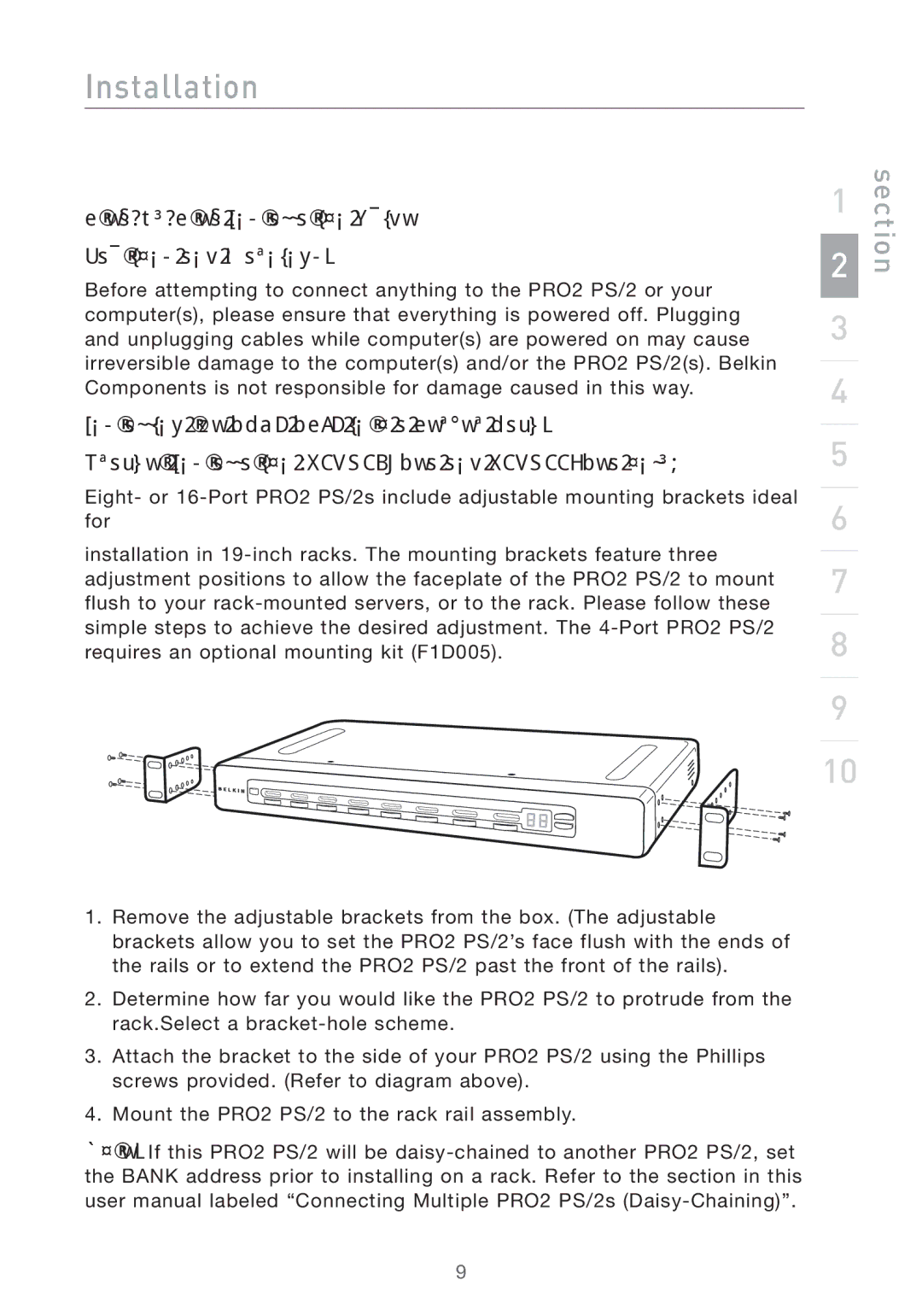
Bracket Installation (F1DA108Pea and F1DA116Pea only)
Eight- or
installation in
1
2
3
4
5
6
7
8
9
10
section
1.Remove the adjustable brackets from the box. (The adjustable brackets allow you to set the PRO2 PS/2’s face flush with the ends of the rails or to extend the PRO2 PS/2 past the front of the rails).
2.Determine how far you would like the PRO2 PS/2 to protrude from the rack.Select a
3.Attach the bracket to the side of your PRO2 PS/2 using the Phillips screws provided. (Refer to diagram above).
4.Mount the PRO2 PS/2 to the rack rail assembly.
Note: If this PRO2 PS/2 will be
9