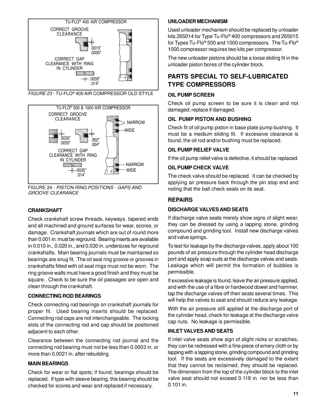
CORRECT GROOVE
CLEARANCE
.0015”
.0030”
CORRECT GAP
CLEARANCE WITH RING
IN CYLINDER
.0035”
.014”
FIGURE 23 - TU-FLO® 400 AIR COMPRESSOR OLD STYLE
TU-FLO® 500 & 1000 AIR COMPRESSOR
CORRECT GROOVE
CLEARANCE
|
| NARROW |
|
| WIDE |
.0035” | .002” |
|
.0035” |
| |
.004” |
| |
|
| |
CORRECT GAP |
|
|
CLEARANCE WITH RING |
| |
IN CYLINDER |
| NARROW |
|
| |
.0035” |
| WIDE |
.014” |
|
|
FIGURE 24 - PISTON RING POSITIONS - GAPS AND GROOVE CLEARANCE
CRANKSHAFT
Check crankshaft screw threads, keyways, tapered ends and all machined and ground surfaces for wear, scores, or damage. Crankshaft journals which are out of round more than 0.001 in. must be reground. Bearing inserts are available in 0.010 in., 0.020 in., and 0.030 in. undersizes for reground crankshafts. Main bearing journals must be maintained so bearings are snug fit. The oil seal ring groove or grooves in crankshafts fitted with oil seal rings must not be worn. The ring groove walls must have a good finish and they must be square. Check to be sure the oil passages are open and clean through the crankshaft.
CONNECTING ROD BEARINGS
Check connecting rod bearings on crankshaft journals for proper fit. Used bearing inserts should be replaced. Connecting rod caps are not interchangeable. The locking slots of the connecting rod and cap should be positioned adjacent to each other.
Clearance between the connecting rod journal and the connecting rod bearing must not be less than 0.0003 in. or more than 0.0021 in. after rebuilding.
MAIN BEARINGS
Check for wear or flat spots; if found, bearings should be replaced. If type with sleeve bearing, this bearing should be checked for scores and wear and replaced if necessary.
UNLOADER MECHANISM
Used unloader mechanism should be replaced by unloader kits 265014 for Type
The new unloader pistons should be a loose sliding fit in the unloader piston bores of the cylinder block.
PARTS SPECIAL TO SELF-LUBRICATED TYPE COMPRESSORS
OIL PUMP SCREEN
Check oil pump screen to be sure it is clean and not damaged; replace if damaged.
OIL PUMP PISTON AND BUSHING
Check fit of oil pump piston in base plate pump bushing. It must be a medium sliding fit. If excessive clearance is found, the oil rod and/or bushing must be replaced.
OIL PUMP RELIEF VALVE
If the oil pump relief valve is defective, it should be replaced.
OIL PUMP CHECK VALVE
The check valve should be replaced. It can be checked by applying air pressure back through the pin stop end and noting that the ball check seals on its seat.
REPAIRS
DISCHARGE VALVES AND SEATS
If discharge valve seats merely show signs of slight wear, they can be dressed by using a lapping stone, grinding compound and grinding tool. Install new discharge valves and valve springs.
To test for leakage by the discharge valves, apply about 100 pounds of air pressure through the cylinder head discharge port and apply soap suds at the discharge valves and seats. Leakage which will permit the formation of bubbles is permissible.
If excessive leakage is found, leave the air pressure applied, and with the use of a fibre or hardwood dowel and hammer, tap the discharge valves off their seats several times. This will help the valves to seat and should reduce any leakage.
With the air pressure still applied at the discharge port of the cylinder head, check for leakage at the discharge valve cap nuts. No leakage is permissible.
INLET VALVES AND SEATS
If inlet valve seats show sign of slight nicks or scratches, they can be redressed with a fine piece of emery cloth or by lapping with a lapping stone, grinding compound and grinding tool. If the seats are excessively damaged to the extent that they cannot be reclaimed, they should be replaced. The dimension from the top of the cylinder block to the inlet valve seat should not exceed 0.118 in. nor be less than 0.101 in.
11