BASEPLATE
SELF-LUBRICATED TYPE COMPRESSORS
Install oil pump piston and rod on crankshaft.
Oil rod bearing fit must be the same as specified for connecting rod bearings. Install oil rod cap nuts and cotter pins to lock oil rod nuts.
Install oil pump relief valve in base plate. The relief valve can be tested at this stage by applying air pressure to the relief valve. The valve should open when the pressure is between 14 psi minimum and 24 psi maximum. When the relief valve is properly installed in the base plate, install set screw that locks it in place.
Place oil pump screen in base and install retaining ring, making sure it snaps in place and secures the screw.
Install oil filter fitting on base plate in its proper place. Install blanking cover on opposite oil filter fitting hole in plate.
Install a new oil seal gasket around oil pump - check valve and position a new base plate gasket on the crankcase. Position base plate assembly on crankcase, making sure oil pump piston engages the oil pump bushing in the base plate. Install and tighten base plate screws.
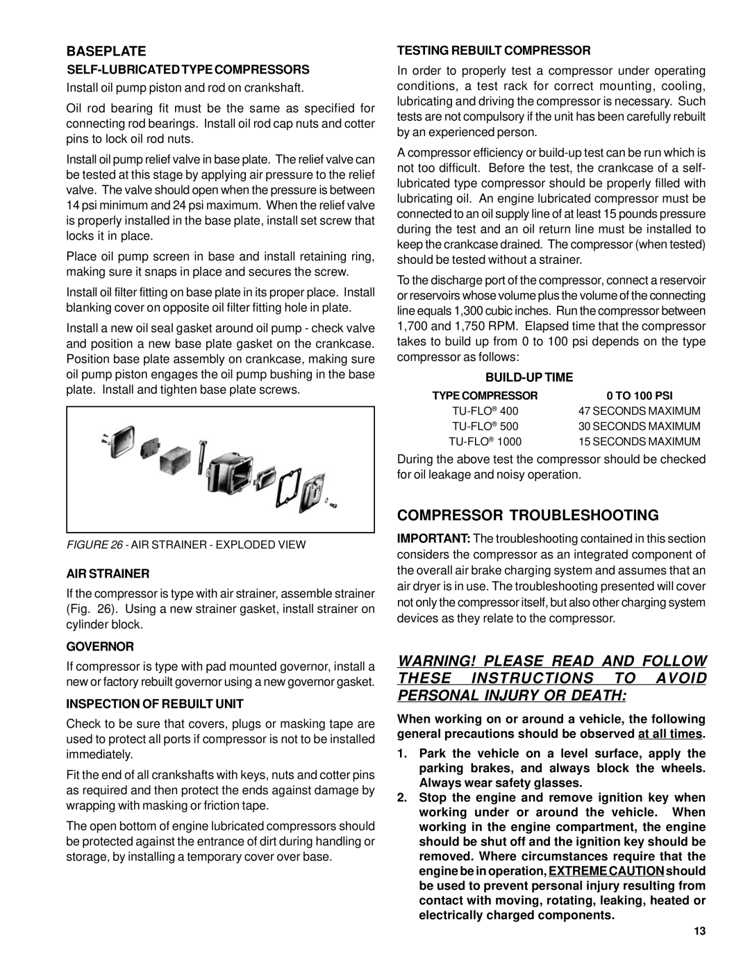
FIGURE 26 - AIR STRAINER - EXPLODED VIEW
AIR STRAINER
If the compressor is type with air strainer, assemble strainer (Fig. 26). Using a new strainer gasket, install strainer on cylinder block.
GOVERNOR
If compressor is type with pad mounted governor, install a new or factory rebuilt governor using a new governor gasket.
INSPECTION OF REBUILT UNIT
Check to be sure that covers, plugs or masking tape are used to protect all ports if compressor is not to be installed immediately.
Fit the end of all crankshafts with keys, nuts and cotter pins as required and then protect the ends against damage by wrapping with masking or friction tape.
The open bottom of engine lubricated compressors should be protected against the entrance of dirt during handling or storage, by installing a temporary cover over base.
TESTING REBUILT COMPRESSOR
In order to properly test a compressor under operating conditions, a test rack for correct mounting, cooling, lubricating and driving the compressor is necessary. Such tests are not compulsory if the unit has been carefully rebuilt by an experienced person.
A compressor efficiency or
To the discharge port of the compressor, connect a reservoir or reservoirs whose volume plus the volume of the connecting line equals 1,300 cubic inches. Run the compressor between 1,700 and 1,750 RPM. Elapsed time that the compressor takes to build up from 0 to 100 psi depends on the type compressor as follows:
BUILD-UP TIME
TYPE COMPRESSOR | 0 TO 100 PSI |
47 SECONDS MAXIMUM | |
30 SECONDS MAXIMUM | |
15 SECONDS MAXIMUM |
During the above test the compressor should be checked for oil leakage and noisy operation.
COMPRESSOR TROUBLESHOOTING
IMPORTANT: The troubleshooting contained in this section considers the compressor as an integrated component of the overall air brake charging system and assumes that an air dryer is in use. The troubleshooting presented will cover not only the compressor itself, but also other charging system devices as they relate to the compressor.
WARNING! PLEASE READ AND FOLLOW THESE INSTRUCTIONS TO AVOID PERSONAL INJURY OR DEATH:
When working on or around a vehicle, the following general precautions should be observed at all times.
1.Park the vehicle on a level surface, apply the parking brakes, and always block the wheels. Always wear safety glasses.
2.Stop the engine and remove ignition key when working under or around the vehicle. When working in the engine compartment, the engine should be shut off and the ignition key should be removed. Where circumstances require that the engine be in operation, EXTREME CAUTION should be used to prevent personal injury resulting from contact with moving, rotating, leaking, heated or electrically charged components.
13
