As the piston reaches the top of its stroke and starts down, the discharge valve spring returns the discharge valve to its seat. This prevents the compressed air in the discharge line from returning to the cylinder bore as the intake and compression cycle is repeated.
NON-COMPRESSION (Unloaded)
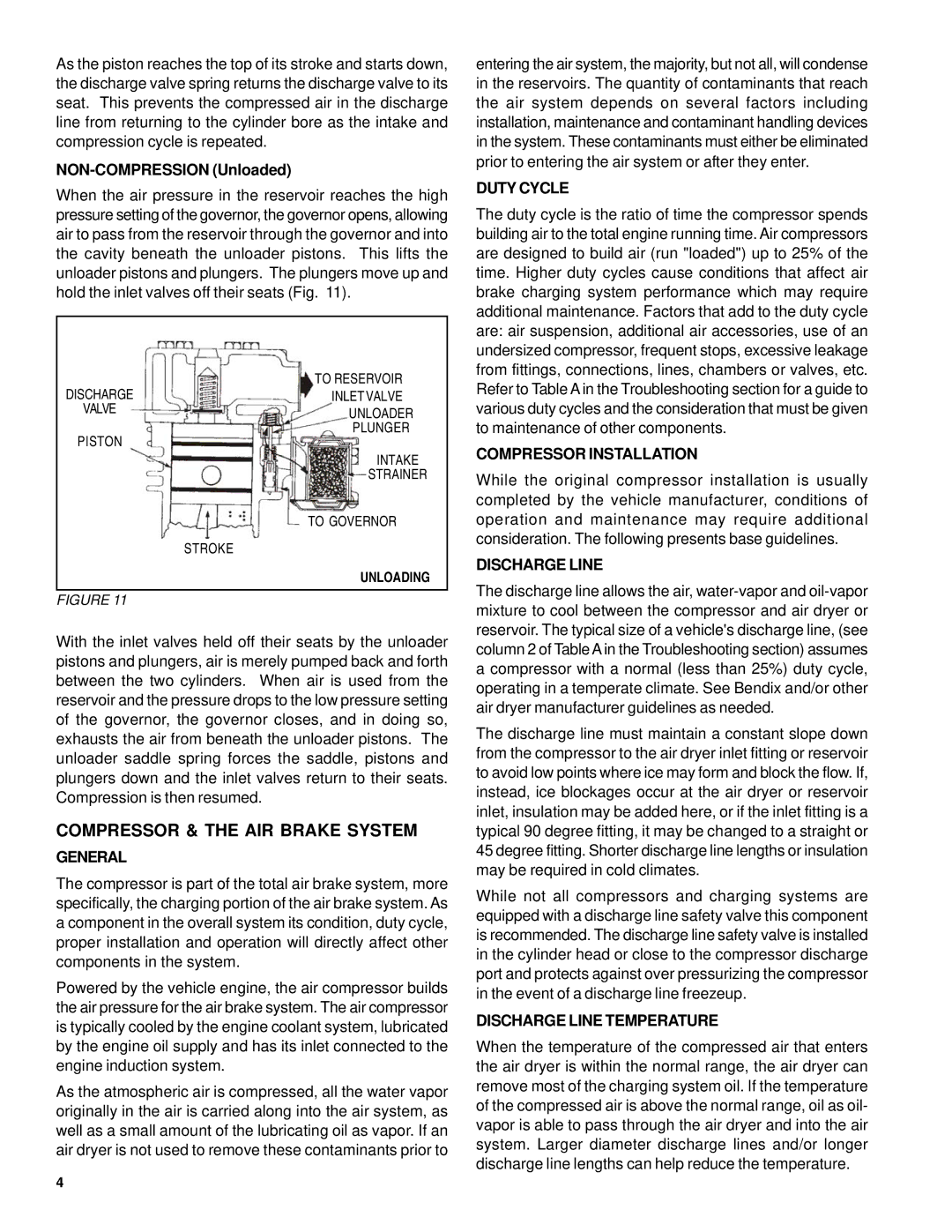
When the air pressure in the reservoir reaches the high pressure setting of the governor, the governor opens, allowing air to pass from the reservoir through the governor and into the cavity beneath the unloader pistons. This lifts the unloader pistons and plungers. The plungers move up and hold the inlet valves off their seats (Fig. 11).
DISCHARGE | TO RESERVOIR |
INLET VALVE | |
VALVE | UNLOADER |
PISTON | PLUNGER |
| |
| INTAKE |
| STRAINER |
| TO GOVERNOR |
| STROKE |
| UNLOADING |
|
|
FIGURE 11 |
|
With the inlet valves held off their seats by the unloader pistons and plungers, air is merely pumped back and forth between the two cylinders. When air is used from the reservoir and the pressure drops to the low pressure setting of the governor, the governor closes, and in doing so, exhausts the air from beneath the unloader pistons. The unloader saddle spring forces the saddle, pistons and plungers down and the inlet valves return to their seats. Compression is then resumed.
COMPRESSOR & THE AIR BRAKE SYSTEM
GENERAL
The compressor is part of the total air brake system, more specifically, the charging portion of the air brake system. As a component in the overall system its condition, duty cycle, proper installation and operation will directly affect other components in the system.
Powered by the vehicle engine, the air compressor builds the air pressure for the air brake system. The air compressor is typically cooled by the engine coolant system, lubricated by the engine oil supply and has its inlet connected to the engine induction system.
As the atmospheric air is compressed, all the water vapor originally in the air is carried along into the air system, as well as a small amount of the lubricating oil as vapor. If an air dryer is not used to remove these contaminants prior to
4
entering the air system, the majority, but not all, will condense in the reservoirs. The quantity of contaminants that reach the air system depends on several factors including installation, maintenance and contaminant handling devices in the system. These contaminants must either be eliminated prior to entering the air system or after they enter.
DUTY CYCLE
The duty cycle is the ratio of time the compressor spends building air to the total engine running time. Air compressors are designed to build air (run "loaded") up to 25% of the time. Higher duty cycles cause conditions that affect air brake charging system performance which may require additional maintenance. Factors that add to the duty cycle are: air suspension, additional air accessories, use of an undersized compressor, frequent stops, excessive leakage from fittings, connections, lines, chambers or valves, etc. Refer to Table A in the Troubleshooting section for a guide to various duty cycles and the consideration that must be given to maintenance of other components.
COMPRESSOR INSTALLATION
While the original compressor installation is usually completed by the vehicle manufacturer, conditions of operation and maintenance may require additional consideration. The following presents base guidelines.
DISCHARGE LINE
The discharge line allows the air,
The discharge line must maintain a constant slope down from the compressor to the air dryer inlet fitting or reservoir to avoid low points where ice may form and block the flow. If, instead, ice blockages occur at the air dryer or reservoir inlet, insulation may be added here, or if the inlet fitting is a typical 90 degree fitting, it may be changed to a straight or 45 degree fitting. Shorter discharge line lengths or insulation may be required in cold climates.
While not all compressors and charging systems are equipped with a discharge line safety valve this component is recommended. The discharge line safety valve is installed in the cylinder head or close to the compressor discharge port and protects against over pressurizing the compressor in the event of a discharge line freezeup.
DISCHARGE LINE TEMPERATURE
When the temperature of the compressed air that enters the air dryer is within the normal range, the air dryer can remove most of the charging system oil. If the temperature of the compressed air is above the normal range, oil as oil- vapor is able to pass through the air dryer and into the air system. Larger diameter discharge lines and/or longer discharge line lengths can help reduce the temperature.