7

8

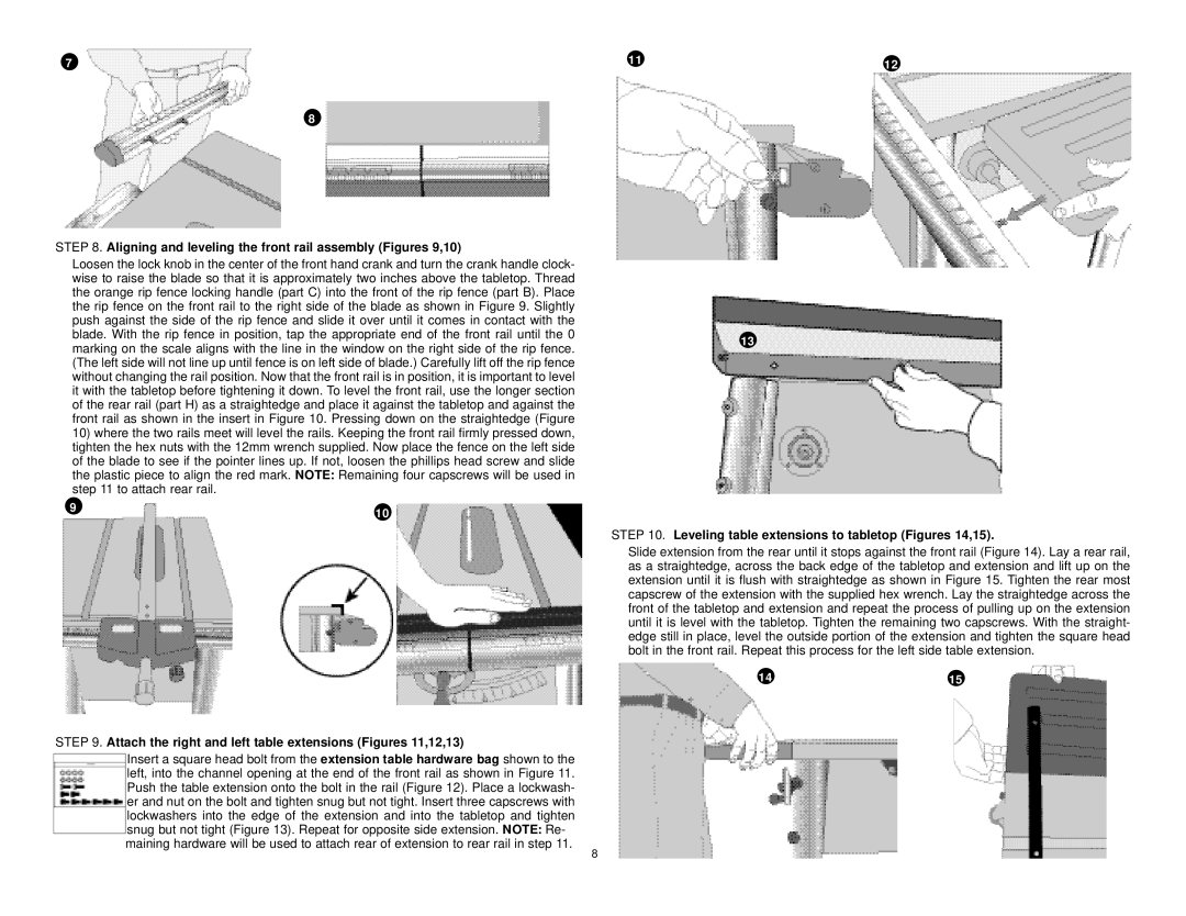
STEP 8. Aligning and leveling the front rail assembly (Figures 9,10)

Loosen the lock knob in the center of the front hand crank and turn the crank handle clock- wise to raise the blade so that it is approximately two inches above the tabletop. Thread the orange rip fence locking handle (part C) into the front of the rip fence (part B). Place the rip fence on the front rail to the right side of the blade as shown in Figure 9. Slightly push against the side of the rip fence and slide it over until it comes in contact with the blade. With the rip fence in position, tap the appropriate end of the front rail until the 0 marking on the scale aligns with the line in the window on the right side of the rip fence. (The left side will not line up until fence is on left side of blade.) Carefully lift off the rip fence without changing the rail position. Now that the front rail is in position, it is important to level it with the tabletop before tightening it down. To level the front rail, use the longer section of the rear rail (part H) as a straightedge and place it against the tabletop and against the front rail as shown in the insert in Figure 10. Pressing down on the straightedge (Figure

10)where the two rails meet will level the rails. Keeping the front rail firmly pressed down, tighten the hex nuts with the 12mm wrench supplied. Now place the fence on the left side of the blade to see if the pointer lines up. If not, loosen the phillips head screw and slide the plastic piece to align the red mark. NOTE: Remaining four capscrews will be used in step 11 to attach rear rail.

9

10


STEP 9. Attach the right and left table extensions (Figures 11,12,13)

Insert a square head bolt from the extension table hardware bag shown to the left, into the channel opening at the end of the front rail as shown in Figure 11. Push the table extension onto the bolt in the rail (Figure 12). Place a lockwash- er and nut on the bolt and tighten snug but not tight. Insert three capscrews with lockwashers into the edge of the extension and into the tabletop and tighten snug but not tight (Figure 13). Repeat for opposite side extension. NOTE: Re- maining hardware will be used to attach rear of extension to rear rail in step 11.

11

12


13

STEP 10. Leveling table extensions to tabletop (Figures 14,15).

Slide extension from the rear until it stops against the front rail (Figure 14). Lay a rear rail, as a straightedge, across the back edge of the tabletop and extension and lift up on the extension until it is flush with straightedge as shown in Figure 15. Tighten the rear most capscrew of the extension with the supplied hex wrench. Lay the straightedge across the front of the tabletop and extension and repeat the process of pulling up on the extension until it is level with the tabletop. Tighten the remaining two capscrews. With the straight- edge still in place, level the outside portion of the extension and tighten the square head bolt in the front rail. Repeat this process for the left side table extension.

14

15

8

Page 8
Image 8
Black & Decker BT2500, 606404-00 instruction manual Aligning and leveling the front rail assembly Figures 9,10

606404-00, BT2500 specifications

The Black & Decker BT2500 (part number 606404-00) is a powerful and versatile tool designed for various home improvement and DIY projects. This product exemplifies the brand's commitment to quality, innovation, and user-friendly design, making it an excellent addition to both amateur and professional toolkits.

One of the standout features of the BT2500 is its robust motor, which delivers exceptional power and efficiency. This ensures that users can complete tasks quickly and effectively, whether they're drilling into tough materials like wood or metal or engaging in more delicate work. The tool's capability to handle a wide range of applications is a significant advantage, as it allows users to use it for multiple projects without needing additional equipment.

The BT2500 also incorporates advanced ergonomic design elements, which enhance user comfort during prolonged use. The soft-grip handle is a key aspect of this design, providing a secure and comfortable grip that reduces hand fatigue. Furthermore, the tool’s lightweight construction allows for easy maneuverability, ensuring that users can work in various positions without straining their bodies.

Another important technological feature of the BT2500 is its variable speed control. This allows users to adjust the speed according to the specific requirements of their projects, ensuring optimal performance and precision. The ability to customize speed settings is particularly useful when working on different materials or when delicate control is required.

Additionally, the BT2500 is equipped with a built-in LED work light. This feature illuminates the workspace, making it easier to see what you are doing, especially in dimly lit conditions. The LED light can significantly improve accuracy and safety while working, reducing the likelihood of errors or accidents.

The tool comes with a range of accessories, further enhancing its versatility. Users can easily switch between different attachments for drilling, driving, or even sanding tasks, making it a multifaceted tool suitable for various home improvement projects.

In summary, the Black & Decker BT2500 (606404-00) is a well-rounded power tool marked by its powerful motor, ergonomic design, variable speed control, and handy built-in LED work light. Its versatility and ease of use make it a valuable asset for anyone looking to tackle home repairs, renovations, or creative DIY endeavors. Whether you are a seasoned professional or a DIY enthusiast, the BT2500 is engineered to meet a wide array of needs, enabling users to achieve satisfying and high-quality results in their projects.