Indoor Pendant & | EN 10 |
|
|
2.2Wire the Connector (Pendant
Housings)
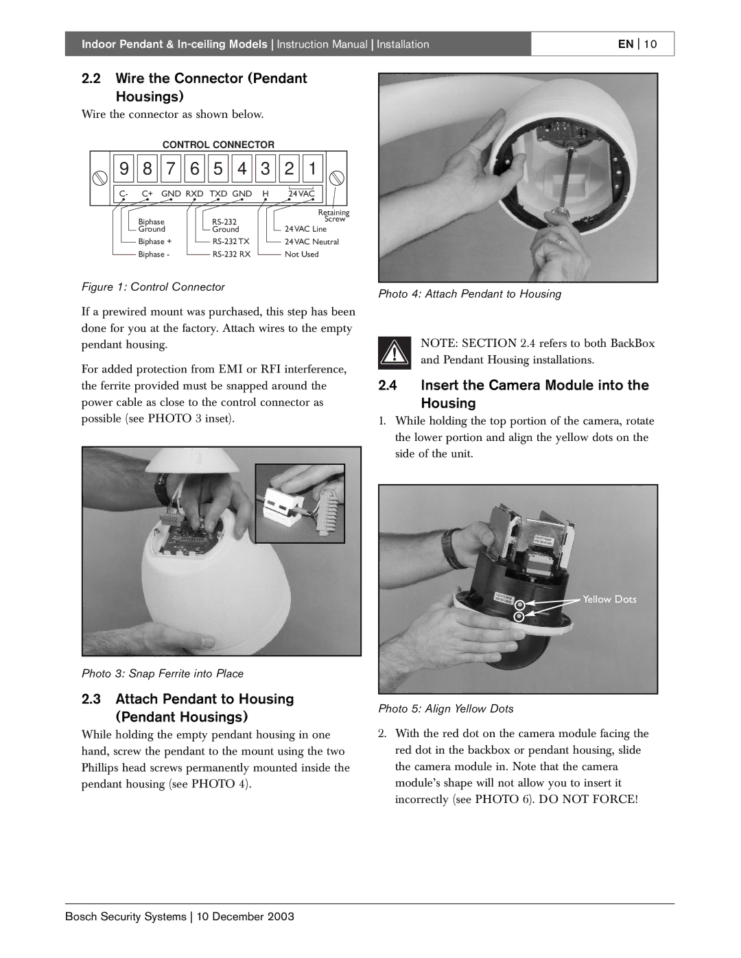
Wire the connector as shown below.
CONTROL CONNECTOR
9 | 8 | 7 | 6 | 5 | 4 | 3 | 2 | 1 |
C- | C+ | GND RXD TXD GND | H | 24 VAC | ||||
|
|
|
|
|
|
|
| Retaining |
| Biphase |
|
|
|
| Screw | ||
| Ground |
| Ground |
| 24 VAC Line | |||
| Biphase + |
|
| 24 VAC Neutral | ||||
| Biphase - |
|
| Not Used | ||||
Figure 1: Control Connector
If a prewired mount was purchased, this step has been done for you at the factory. Attach wires to the empty pendant housing.
For added protection from EMI or RFI interference, the ferrite provided must be snapped around the power cable as close to the control connector as possible (see PHOTO 3 inset).
Photo 3: Snap Ferrite into Place
2.3Attach Pendant to Housing
(Pendant Housings)
While holding the empty pendant housing in one hand, screw the pendant to the mount using the two Phillips head screws permanently mounted inside the pendant housing (see PHOTO 4).
Photo 4: Attach Pendant to Housing
NOTE: SECTION 2.4 refers to both BackBox and Pendant Housing installations.
2.4Insert the Camera Module into the
Housing
1.While holding the top portion of the camera, rotate the lower portion and align the yellow dots on the side of the unit.
![]() Yellow Dots
Yellow Dots
Photo 5: Align Yellow Dots
2.With the red dot on the camera module facing the red dot in the backbox or pendant housing, slide the camera module in. Note that the camera module’s shape will not allow you to insert it incorrectly (see PHOTO 6). DO NOT FORCE!
Bosch Security Systems 10 December 2003
