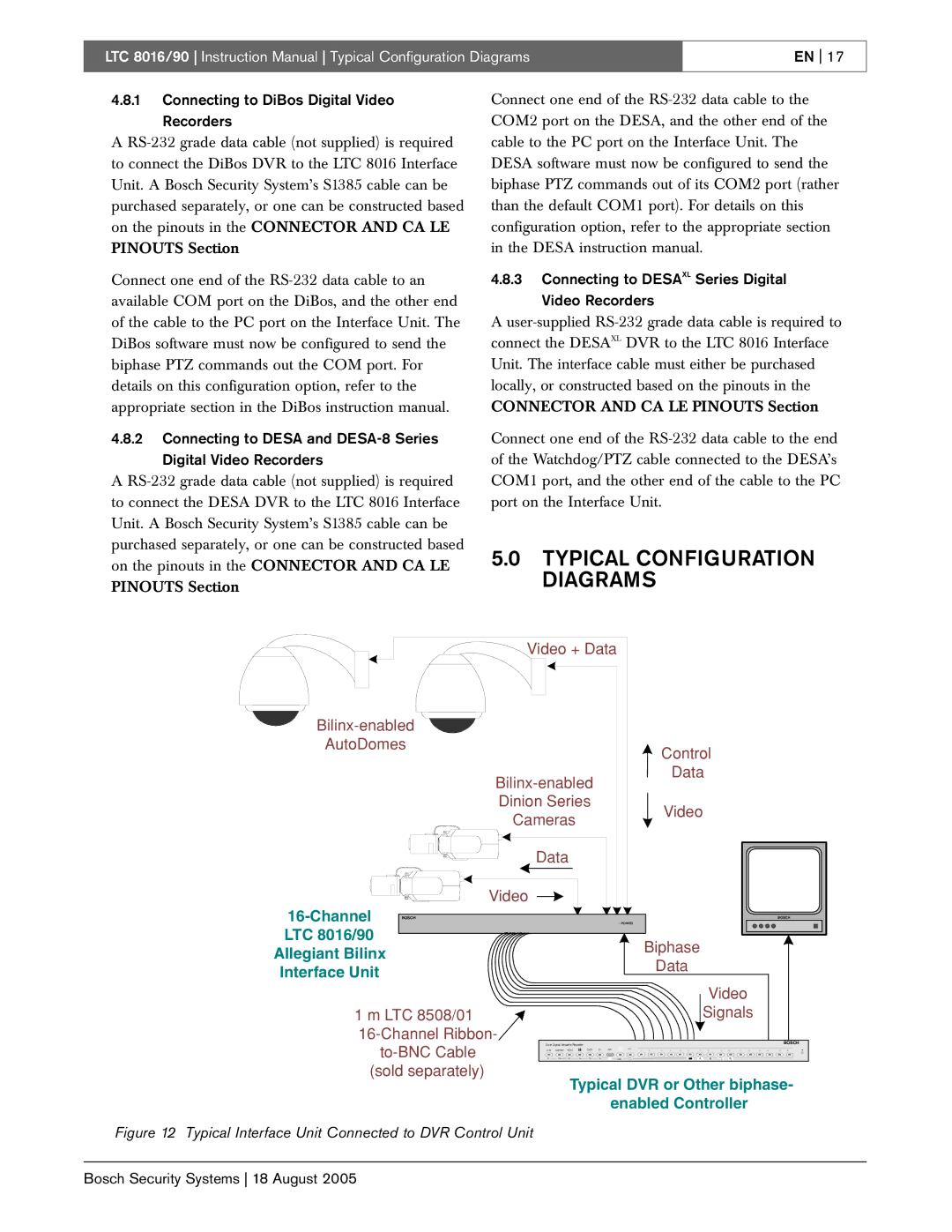
LTC 8016/90 specifications
The Bosch Appliances LTC 8016/90 is a standout refrigerator that embodies innovation and efficiency, designed to meet the diverse needs of modern households. With its sleek design and advanced features, this appliance not only enhances the aesthetics of your kitchen but also elevates your food storage experience.One of the key features of the LTC 8016/90 is its spacious interior, which offers ample storage capacity for groceries and other food items. The flexible shelving system is customizable, allowing users to adjust the height and configuration of the shelves to accommodate taller items or bulkier groceries with ease. This adaptability ensures that every inch of space is utilized effectively, making it ideal for family-sized loads.
The refrigerator incorporates Bosch’s innovative VitaFresh technology, which helps to keep fruits and vegetables fresher for longer periods. This is achieved through optimal humidity control and temperature regulation, significantly extending the shelf life of perishable items. The dual-zone cooling system is another technological advancement, providing temperature stability for both the refrigerator and the freezer compartments, ensuring that food maintains its freshness without the risk of frost buildup.
Energy efficiency is a hallmark of the LTC 8016/90, as it comes with an excellent energy rating that not only contributes to lower energy bills but also minimizes your carbon footprint. This refrigerator is equipped with an EcoMode feature that further reduces energy consumption when the appliance is not in regular use, making it an environmentally conscious choice.
Safety and convenience are also prioritized in this Bosch model. The integrated LED lighting illuminates the interior, allowing for easy visibility of stored items, while the ergonomic handle design ensures effortless access. Additionally, the appliance is equipped with a multi-airflow system that circulates cool air evenly throughout the compartments, preventing hotspots and ensuring consistent cooling.
In terms of maintenance, the LTC 8016/90 boasts a removable water filter and an easy-to-clean interior, making upkeep a breeze. The appliance's minimalist yet functional design complements any kitchen décor, making it a versatile addition to your home.
Overall, the Bosch Appliances LTC 8016/90 refrigerator stands out for its advanced features, energy efficiency, and modern design, making it an excellent choice for those seeking quality and reliability in their kitchen appliances. Whether you’re a culinary enthusiast or simply looking for a dependable refrigerator, the LTC 8016/90 delivers on all fronts, ensuring that your food storage needs are met with precision and style.

