generator or converter to the power consumer must be rated so that the
§9 N will at least be activated when- ever a complete short circuit bet- ween an outer conductor and the neutral conductor occurs at any point in the circuitry.
One can also use fault current cir- cuit breakers in addition, as shown in Fig. 6 (illustrated, for the sake of simplicity, for
The relay coil in the FI circuit breaker is activated (Fig. 7). 45 mA FI circuit breakers are available for 265 V/200 Hz rotary current. FI circuit breakers for rotary current at other voltage and frequency levels must be specially requested from appropriate manufacturers.
A schematic representation of an FI circuit breaker is provided in Fig. 8. In order to accommo- date the regulations and specific conditions in other countries, Bosch offers
voltages (265 V, 135 V, 72 V, 42 V at 200 Hz; 200 V, 72 V, 42 V at 300 Hz). At the lower voltages, however, only a few
be too large.
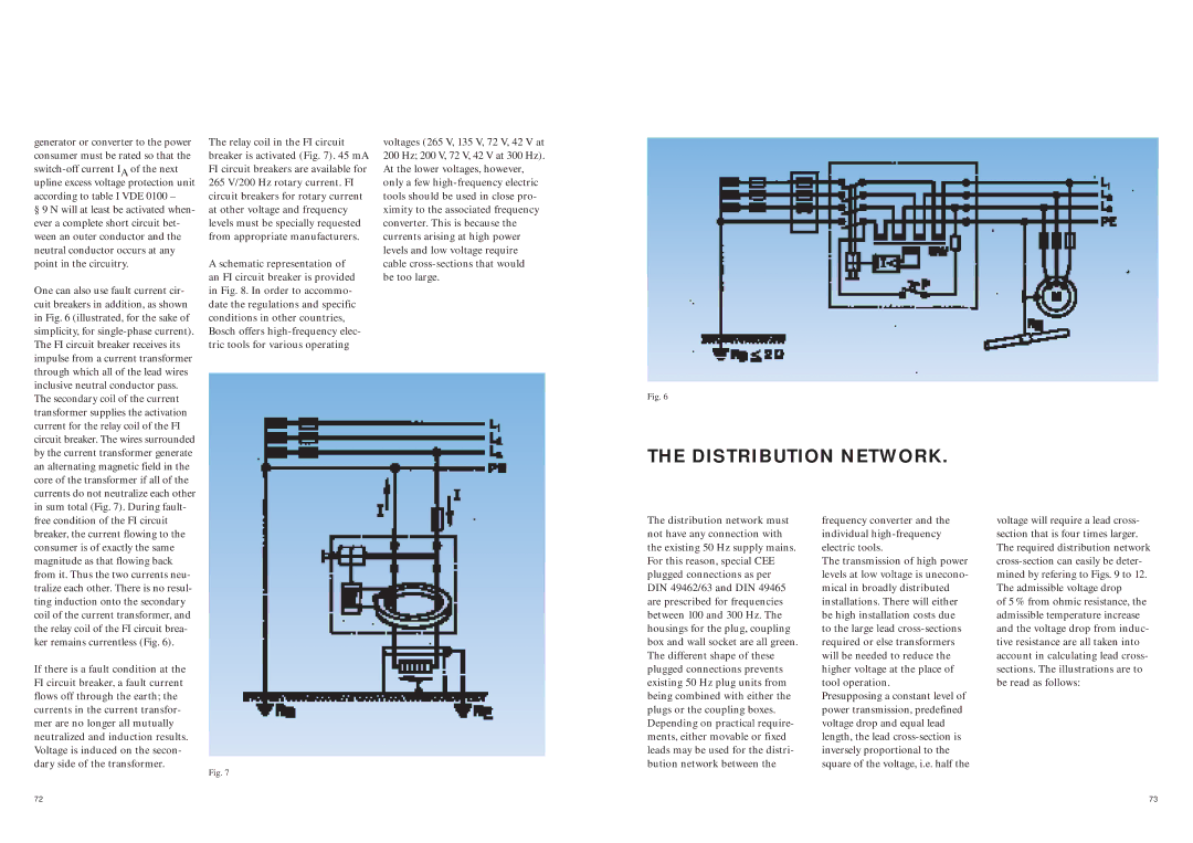
Fig. 6
THE DISTRIBUTION NETWORK.
free condition of the FI circuit breaker, the current flowing to the consumer is of exactly the same magnitude as that flowing back from it. Thus the two currents neu- tralize each other. There is no resul- ting induction onto the secondary coil of the current transformer, and the relay coil of the FI circuit brea- ker remains currentless (Fig. 6).
If there is a fault condition at the FI circuit breaker, a fault current flows off through the earth; the currents in the current transfor- mer are no longer all mutually neutralized and induction results. Voltage is induced on the secon- dary side of the transformer.
The distribution network must not have any connection with the existing 50 Hz supply mains. For this reason, special CEE plugged connections as per DIN 49462/63 and DIN 49465 are prescribed for frequencies between 100 and 300 Hz. The housings for the plug, coupling box and wall socket are all green. The different shape of these plugged connections prevents existing 50 Hz plug units from being combined with either the plugs or the coupling boxes. Depending on practical require- ments, either movable or fixed leads may be used for the distri- bution network between the
frequency converter and the individual
The transmission of high power levels at low voltage is unecono- mical in broadly distributed installations. There will either be high installation costs due to the large lead
Presupposing a constant level of power transmission, predefined voltage drop and equal lead length, the lead
voltage will require a lead cross- section that is four times larger. The required distribution network
of 5 % from ohmic resistance, the admissible temperature increase and the voltage drop from induc- tive resistance are all taken into account in calculating lead cross- sections. The illustrations are to be read as follows:
72
Fig. 7
73