DESIGNING AN INSTALLATION FOR HIGH-FREQUENCY ELECTRIC TOOLS.
Frequency converter with synchronic generator
The best solution, technically speaking, in selecting frequency converters is the combination of asynchronic motors with synchronic generators. The con- verters are
The voltage difference between idling and operation under full load is only approx. 3 % for small transformers at cos f 0.6 – 0.9, for large converters, approx. 4 %. Synchronic converters are not affected by voltage fluctuations in the primary rotary current mains and, in addition, safeguarded against short circuiting. Assimila- tion to the rated voltage can be effected by means of a potentio- meter. Moreover, the converters are
Secondary frequency is calcu- lated according to the following formula:
if2 = f1 · p2 /p1
f1 = primary frequency of rotary current mains
f2 = secondary frequency for
p1 = pole pair count of the drive motor
p2 = pole pair count of the generator
Frequency converters with a power output in excess of 4 kVA should generally not be switched into the mains direct but con-
nected by means of star delta switches. When they are switched in directly, a
When a star delta switch is used, the coil of the drive motor is switched from the star
Parallel operation of frequency converters
In order to increase the economics of the entire installation and to equalize load peaks, frequency converters can be switched in parallel. This results in optimal assimilation to the equipment being used. When frequency con- verters are linked to synchronic generators, no particular prepara- tions are required to operate equipment in parallel even when power output levels differ.
Compensating for reactive current
Every inductive consumer is lumbered with a reactive current that performs no effective work, but only loads the electrical wiring. Frequency converters and
Compensation for reactive current on the secondary side of the converter requires considerable expenditure since each tool must be compensated separately. Depending on the number and the performance level of the individual
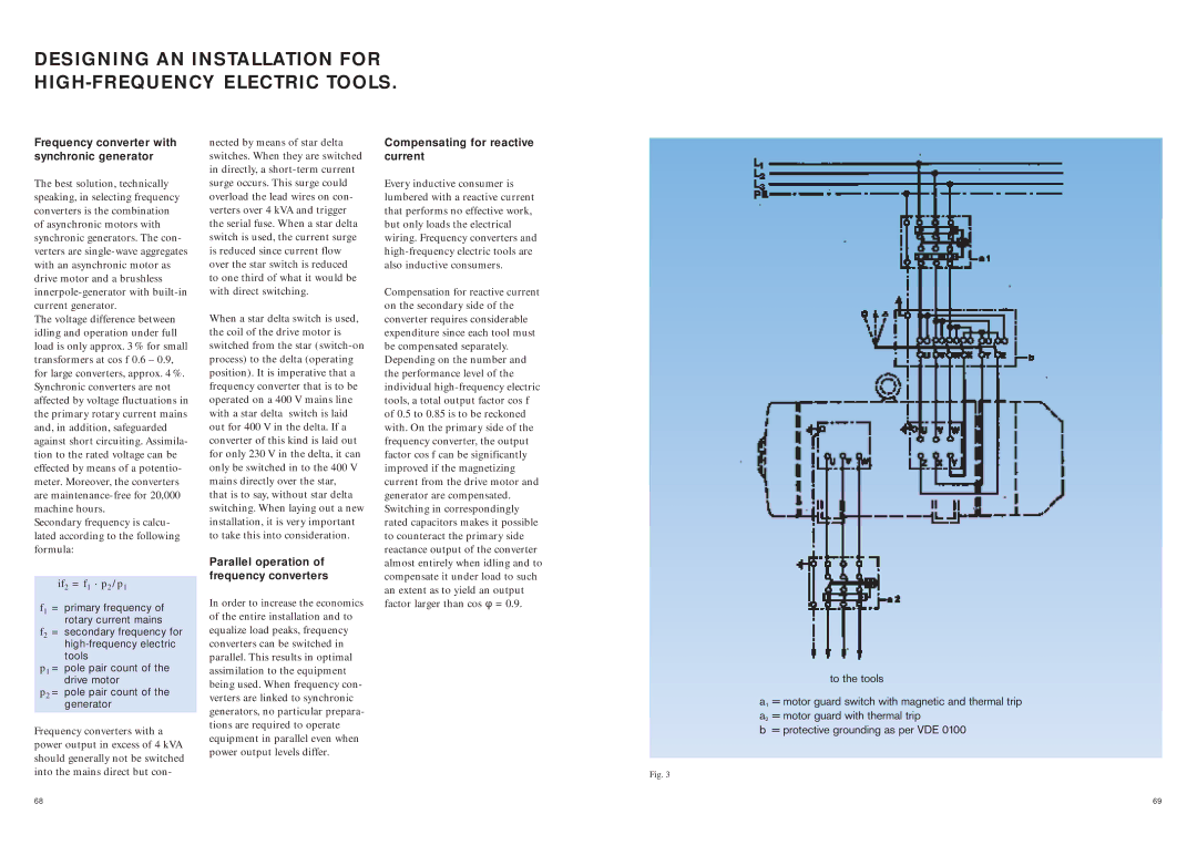
Fig. 3
to the tools
a1 = motor guard switch with magnetic and thermal trip a2 = motor guard with thermal trip
b = protective grounding as per VDE 0100
68 | 69 |