RELIABLE
ELECTRICAL OPERATING VALUES.
A magnetic field forms in a three- phase current motor, which circu- lates through the motor. This is called a rotary field and is depen- dent on the number of pole pairs and frequency. When the smallest possible number of pole pairs is used, at a frequency of 50 Hz, for example, a rotary field or rotor speed of 3000 rpm results; at a fre- quency of 200 Hz: 12000 rpm and at 300 Hz: 18000 rpm.
 Optimum performance in a
 light-weight tool
During extended operation, Bosch
achieve a longer service life.
 Minimal maintenance cost combined with high load capacity
Bosch
An operating frequency of 300 Hz is to be recommended for a high- frequency electric tool installa- tion. The higher motor rotational speed at 300 Hz is particularly advantageous at today's circum- ference velocities for grinders. The increased motor rotational speed results in higher machine performance without an increase in weight. In so far as possible,
For the simultaneity factor G, we | Sample calculation for a | |
have the following experiential |
|
|
values: |
| tool installation |
automobile body |
|
|
manufacture | 0.45 | A foundry wishes to introduce |
motor manufacture | 0.30 | 3 |
appliance manufacture | 0.40 | angle grinders with 230 mm |
tool and form manufacture | 0.25 | diameter cutting discs and 3 high- |
steel manufacture | 0.50 | frequency 0 602 242 134 straight |
foundry work | 0.60 | grinders with 100 mm diameter |
|
| grinding discs. |
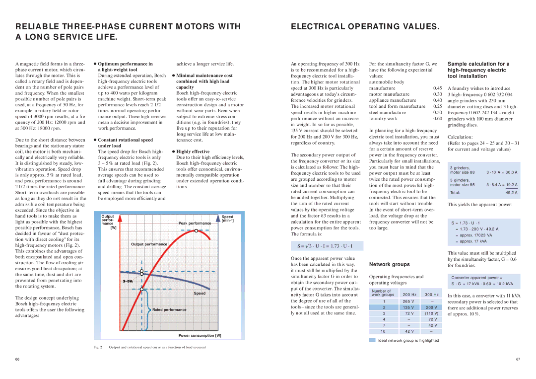
Due to the short distance between bearings and the stationary stator coil, the motor is both mechani- cally and electrically very reliable. It is distinguished by steady, low- vibration operation. Speed drop is only approx. 5 % at rated load, and peak performance is around
2 1/2 times the rated performance.
 Constant rotational speed under load
The speed drop for Bosch high- frequency electric tools is only 3 – 5 % at rated load (Fig. 2). This ensures that recommended average speeds can be used to full advantage during grinding and drilling. The constant average speed means that the tools can be employed more efficiently and
long service life at low main- tenance cost.
 Highly effective
Due to their high efficiency levels, Bosch
135 V current should be selected for 200 Hz and 200 V for 300 Hz, regardless of country.
The secondary power output of the frequency converter or its size is calculated as follows: The high- frequency electric tools to be used are grouped according to motor size and number so that their rated current consumption can be added together. Multiplying the sum of the rated current values by the operating voltage
In planning for a
Calculation:
(Refer to pages 24 – 25 and 30 – 31 for current and voltage values)
3 grinders, |
|
|
|
motor size 88 | 3 · 10 A = 30.0 A | ||
3 girnders, |
|
|
|
motor size 85 | 3 · 6.4 A = 19.2 A | ||
Total: |
| 49.2 A |
|
|
|
|
|
This yields the apparent power:
hand tools is to make them as light as possible with the highest possible performance, Bosch has decided in favour of “dust protec- tion with direct cooling" for its
Output | Speed |
perfor- | |
mance | Peak performance |
[W] |
|
| Output performance |
and the factor ö3 results in a calculation for the entire apparent power consumption for the tools. The formula is:
S = ö3 · U · I = 1.73 · U · I
load, the voltage drop at the frequency converter will not be too large.
S = 1.73 · U · 1
=1.73 · 200 V · 49.2 A
=approx. 17023 VA
=approx. 17 kVA
both encapsulated and open con- struction. The flow of cooling air ensures good heat dissipation; at the same time, dust and dirt are prevented from penetrating into the rotating system.
The design concept underlying Bosch
Speed
Rated performance
Once the apparent power value has been calculated in this way, it must still be multiplied by the simultaneity factor G in order to obtain the secondary power out- put of the converter. The simulta- neity factor G takes into account the degree of use of all of the tools – since the tools are general- ly not all used at the same time.
Network groups
Operating frequencies and operating voltages
Number of | 200 | Hz | 300 Hz | |
work groups | ||||
1 | 265 | V | – |
|
|
|
|
|
|
2 | 135 | V | 200 | V |
3 | 72 V | (110 | V) | |
4 | – |
| 72 V | |
7 | – |
| 42 | V |
10 | 42 | V | – |
|
This value must still be multiplied by the simultaneity factor, G = 0.6 for foundries:
Converter apparent power =
S · G = 17 kVA · 0.60 = 10.2 kVA
In this case, a converter with 11 kVA secondary power is selected so that there are additional power reserves of approx. 10 %.
Power consumption [W]
Fig. 2 Output and rotational speed curve as a function of load moment
Ideal network group is highlighted
66 | 67 |
