Basic Saw Operations
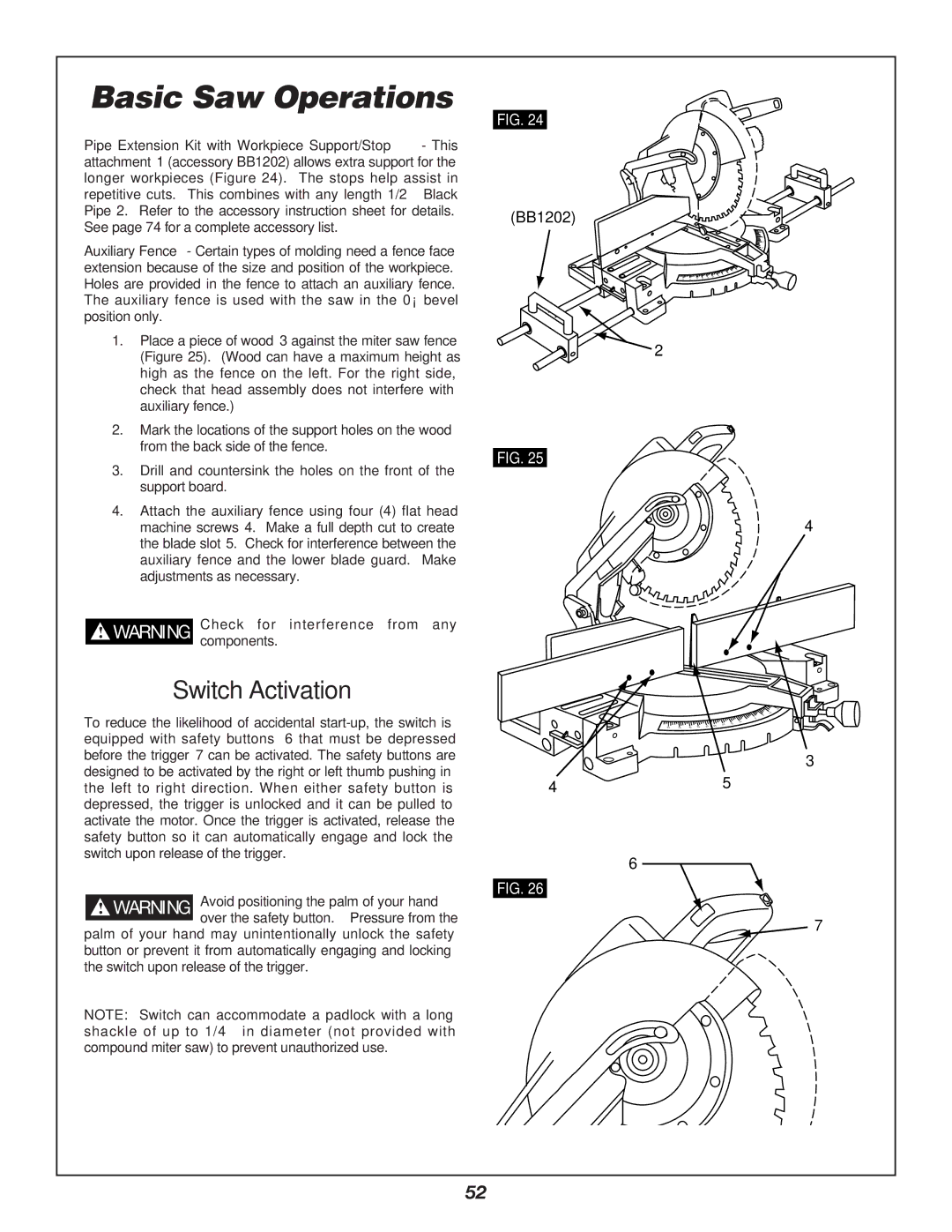
Pipe Extension Kit with Workpiece Support/Stop - This attachment 1 (accessory BB1202) allows extra support for the longer workpieces (Figure 24). The stops help assist in repetitive cuts. This combines with any length 1/2” Black Pipe 2. Refer to the accessory instruction sheet for details. See page 74 for a complete accessory list.
Auxiliary Fence - Certain types of molding need a fence face extension because of the size and position of the workpiece. Holes are provided in the fence to attach an auxiliary fence. The auxiliary fence is used with the saw in the 0° bevel position only.
1.Place a piece of wood 3 against the miter saw fence (Figure 25). (Wood can have a maximum height as high as the fence on the left. For the right side, check that head assembly does not interfere with auxiliary fence.)
2.Mark the locations of the support holes on the wood from the back side of the fence.
3.Drill and countersink the holes on the front of the support board.
4.Attach the auxiliary fence using four (4) flat head machine screws 4. Make a full depth cut to create the blade slot 5. Check for interference between the auxiliary fence and the lower blade guard. Make adjustments as necessary.
!WARNING Check for interference from any components.
Switch Activation
To reduce the likelihood of accidental
! WARNING Avoid positioning the palm of your hand over the safety button. Pressure from the
palm of your hand may unintentionally unlock the safety button or prevent it from automatically engaging and locking the switch upon release of the trigger.
NOTE: Switch can accommodate a padlock with a long shackle of up to 1/4” in diameter (not provided with compound miter saw) to prevent unauthorized use.
FIG. 24
(BB1202)
5 4
2
FIG. 25
4
10
5
0
10
|
|
|
| 30 | 25 | 20 | 15 |
50 | 45 | 40 | 35 |
| |||
|
|
|
|
3
45
6
FIG. 26
![]() 7
7
52