System Setup
Connecting recording equipment
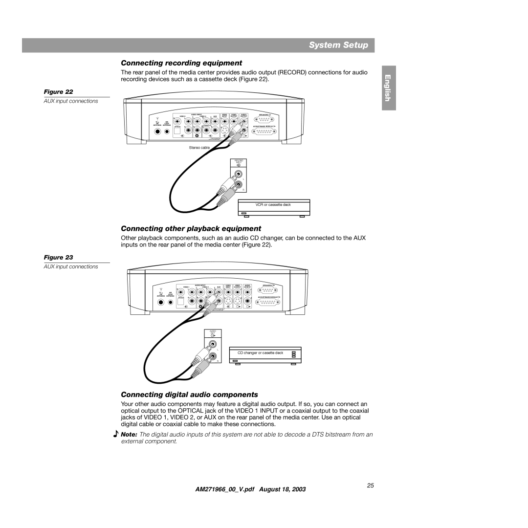
The rear panel of the media center provides audio output (RECORD) connections for audio recording devices such as a cassette deck (Figure 22).
Figure 22
AUX input connections
|
| VIDEO I | AUDIO INPUT | AUX | VIDEO | VIDEO | AUDIO | SPEAKERS | ||
|
|
| VIDEO 2 | INPUT | OUTPUT | OUTPUT |
| |||
| D |
| L | L | D | L | C | C | L |
|
75 Ω | AM |
|
|
|
|
|
|
|
|
|
FM | LOOP |
|
|
|
|
|
|
|
|
|
ANTENNA | ANTENNA | OPTICAL | R | R | D | R |
|
|
| ACOUSTIMASS MODULE |
|
| S | S | R | ||||||
|
|
|
| |||||||
Stereo cable
RECORD
INPUT
L
R
VCR or cassette deck
Connecting other playback equipment
Other playback components, such as an audio CD changer, can be connected to the AUX inputs on the rear panel of the media center (Figure 22).
Figure 23
AUX input connections
|
|
|
| AUDIO INPUT |
| VIDEO | VIDEO | AUDIO | SPEAKERS | |
|
| VIDEO I |
| VIDEO 2 | AUX | INPUT | OUTPUT | OUTPUT |
| |
| D |
| L | L | D | L | C | C | L |
|
75 Ω | AM |
|
|
|
|
|
|
|
|
|
FM | LOOP |
|
|
|
|
|
|
|
|
|
ANTENNA | ANTENNA | OPTICAL | R | R | D | R |
|
|
| ACOUSTIMASS MODULE |
|
| S | S | R | ||||||
AUDIO
OUT
L
CD changer or casette deck
R
English
Connecting digital audio components
Your other audio components may feature a digital audio output. If so, you can connect an optical output to the OPTICAL jack of the VIDEO 1 INPUT or a coaxial output to the coaxial jacks of VIDEO 1, VIDEO 2, or AUX on the rear panel of the media center. Use an optical digital cable or coaxial cable to make these connections.
![]() Note: The digital audio inputs of this system are not able to decode a DTS bitstream from an external component.
Note: The digital audio inputs of this system are not able to decode a DTS bitstream from an external component.
AM271966_00_V.pdf August 18, 2003
25
