Regulator
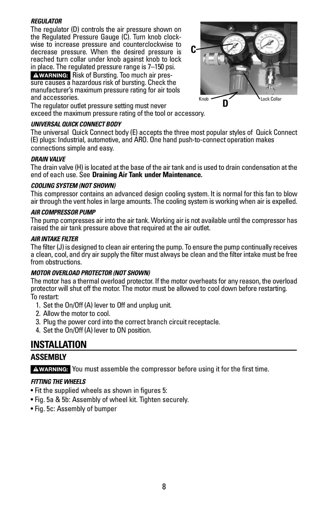
The regulator (D) controls the air pressure shown on the Regulated Pressure Gauge (C). Turn knob clock- wise to increase pressure and counterclockwise to C decrease pressure. When the desired pressure is reached turn collar under knob against knob to lock
in place. The regulated pressure range is
Risk of Bursting. Too much air pres- |
|
|
sure causes a hazardous risk of bursting. Check the |
|
|
manufacturer’s maximum pressure rating for air tools |
|
|
and accessories. | Knob | D |
The regulator outlet pressure setting must never |
|
exceed the maximum pressure rating of the tool or accessory.
Universal Quick Connect BodY
Lock Collar
The universal Quick Connect body (E) accepts the three most popular styles of Quick Connect
(E)plugs: Industrial, automotive, and ARO. One hand
Drain Valve
The drain valve (H) is located at the base of the air tank and is used to drain condensation at the end of each use. See Draining Air Tank under Maintenance.
Cooling System (NOT SHOWN)
This compressor contains an advanced design cooling system. It is normal for this fan to blow air through the vent holes in large amounts. The cooling system is working when air is expelled.
Air Compressor Pump
The pump compresses air into the air tank. Working air is not available until the compressor has raised the air tank pressure above that required at the air outlet.
AIR INTAKE FILTER
The filter (J) is designed to clean air entering the pump. To ensure the pump continually receives a clean, cool, and dry air supply the filter must always be clean and the filter intake must be free from obstructions.
Motor Overload Protector (NOT SHOWN)
The motor has a thermal overload protector. If the motor overheats for any reason, the overload protector will shut off the motor. The motor must be allowed to cool down before restarting.
To restart:
1.Set the On/Off (A) lever to Off and unplug unit.
2.Allow the motor to cool.
3.Plug the power cord into the correct branch circuit receptacle.
4.Set the On/Off (A) lever to ON position.
INSTALLATION
Assembly
You must assemble the compressor before using it for the first time.
Fitting the wheels
•Fit the supplied wheels as shown in figures 5:
•Fig. 5a & 5b: Assembly of wheel kit. Tighten securely.
•Fig. 5c: Assembly of bumper
8