SAVE THESE INSTRUCTIONS FOR FUTURE USE
|
|
|
|
|
|
|
|
|
|
|
|
|
|
|
|
|
|
|
|
|
|
|
|
|
|
|
|
| f |
|
|
| C |
|
| B | J |
| |||
|
|
|
|
|
|
|
|
| |||||
|
|
|
|
|
|
|
|
|
|
| |||
|
|
| E |
|
|
|
|
|
|
|
|
|
|
|
|
|
|
|
|
|
|
|
|
| |||
|
|
| D |
|
| G | I |
|
|
|
|
|
|
|
|
|
|
| C |
| |||||||
|
|
|
|
|
|
|
|
| |||||
|
|
|
|
|
|
|
|
|
|
| |||
|
|
|
|
|
|
|
|
|
|
|
|
|
|
| H |
|
|
|
|
|
|
|
|
| B |
| |
|
|
|
|
|
|
|
|
|
|
|
|
| |
|
|
|
|
|
|
|
|
|
|
|
|
|
|
|
|
|
|
|
|
|
|
|
|
|
|
|
|
|
|
|
|
|
|
|
|
|
|
|
|
|
|
| A |
|
|
|
|
|
|
|
|
|
|
|
|
|
|
|
|
|
|
|
|
|
|
|
|
|
|
|
|
|
|
|
|
|
|
|
|
|
|
|
|
|
|
|
|
|
|
|
| H |
|
|
|
| |
|
|
|
|
|
|
|
|
|
|
|
| ||
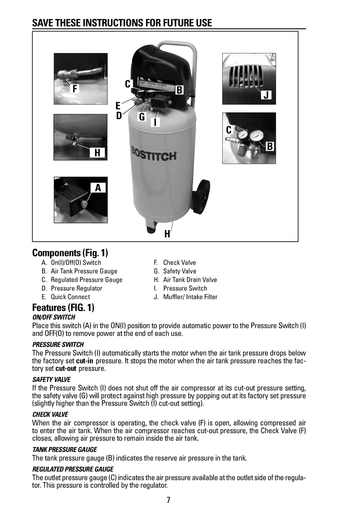
Components (Fig. 1) |
|
|
|
|
|
|
|
|
| ||||
A. On(I)/Off(O) Switch |
|
| F. | Check Valve |
|
|
|
| |||||
B. Air Tank Pressure Gauge |
|
| G. | Safety Valve |
|
|
|
| |||||
C. Regulated Pressure Gauge |
|
| H. | Air Tank Drain Valve |
|
|
|
| |||||
D. Pressure Regulator |
|
| I. | Pressure Switch |
|
|
|
| |||||
E. Quick Connect |
|
| J. | Muffler/ Intake Filter |
|
|
|
| |||||
Features (FIG. 1)
ON/OFF SWITCH
Place this switch (A) in the ON(I) position to provide automatic power to the Pressure Switch (I) and OFF(O) to remove power at the end of each use.
Pressure Switch
The Pressure Switch (I) automatically starts the motor when the air tank pressure drops below the factory set
Safety Valve
If the Pressure Switch (I) does not shut off the air compressor at its
Check Valve
When the air compressor is operating, the check valve (F) is open, allowing compressed air to enter the air tank. When the air compressor reaches
Tank Pressure Gauge
The tank pressure gauge (B) indicates the reserve air pressure in the tank.
regulated Pressure Gauge
The outlet pressure gauge (C) indicates the air pressure available at the outlet side of the regula- tor. This pressure is controlled by the regulator.
7