Remote Mounting the Setback Control
Prepare the Backplate for Wiring
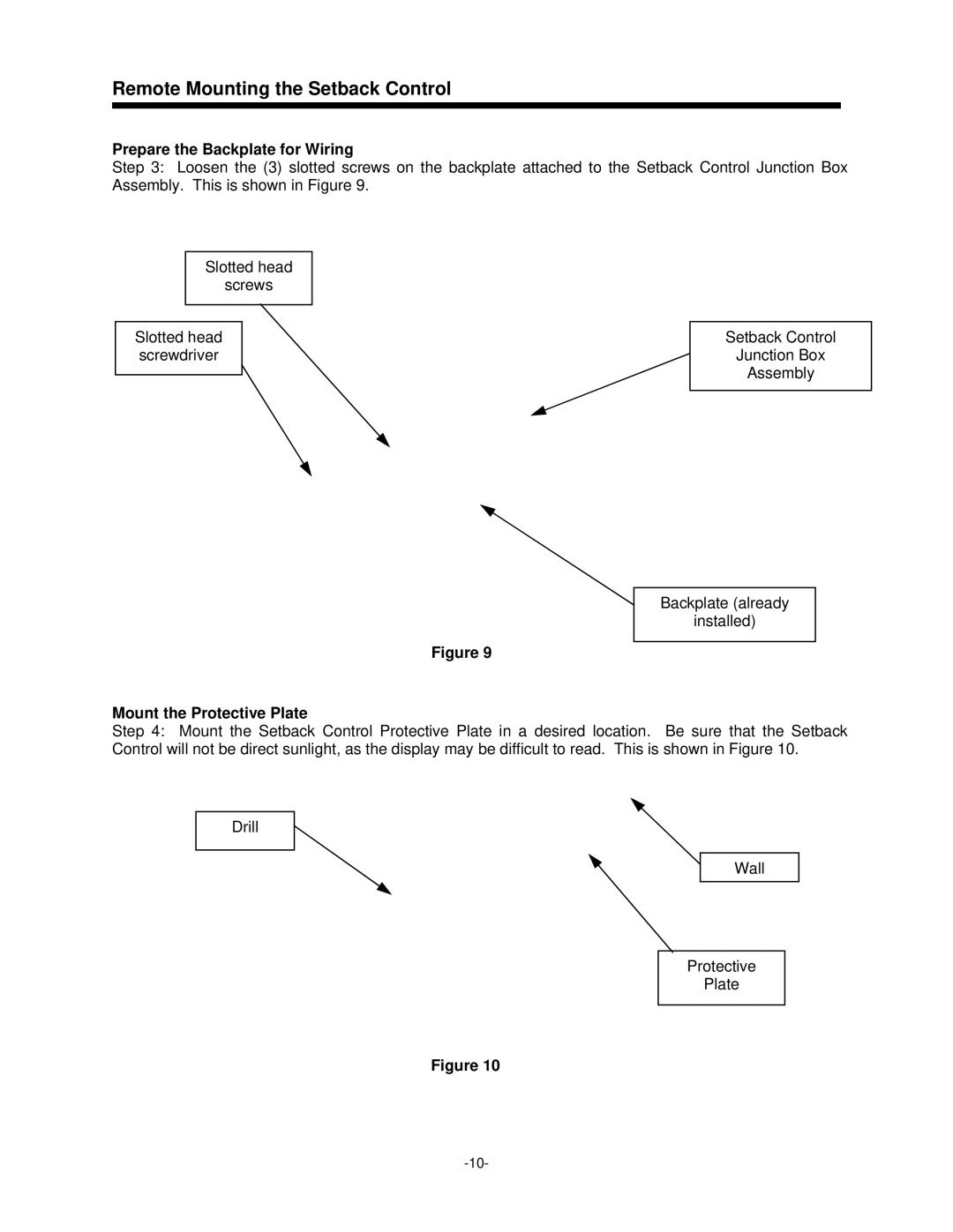
Step 3: Loosen the (3) slotted screws on the backplate attached to the Setback Control Junction Box Assembly. This is shown in Figure 9.
Slotted head
screws
Slotted head screwdriver
Setback Control
Junction Box
Assembly
Backplate (already
installed)
Figure 9
Mount the Protective Plate
Step 4: Mount the Setback Control Protective Plate in a desired location. Be sure that the Setback Control will not be direct sunlight, as the display may be difficult to read. This is shown in Figure 10.
Drill
Wall
Protective
Plate
Figure 10