Manuals
/
Bradford-White Corp
/
Household Appliance
/
Water Heater
Bradford-White Corp
EF Series
warranty
Typical Two Water Heater Connection
Models:
EF Series
1
14
46
46
Download
46 pages
43.04 Kb
11
12
13
14
15
16
17
18
Troubleshooting
Specifications
Install
Parts list
Wiring Diagram and Schematic
Maintenance
Temperature Adjustm NT
Power Vent Maximum Vent Length
Features
Page 14
Image 14
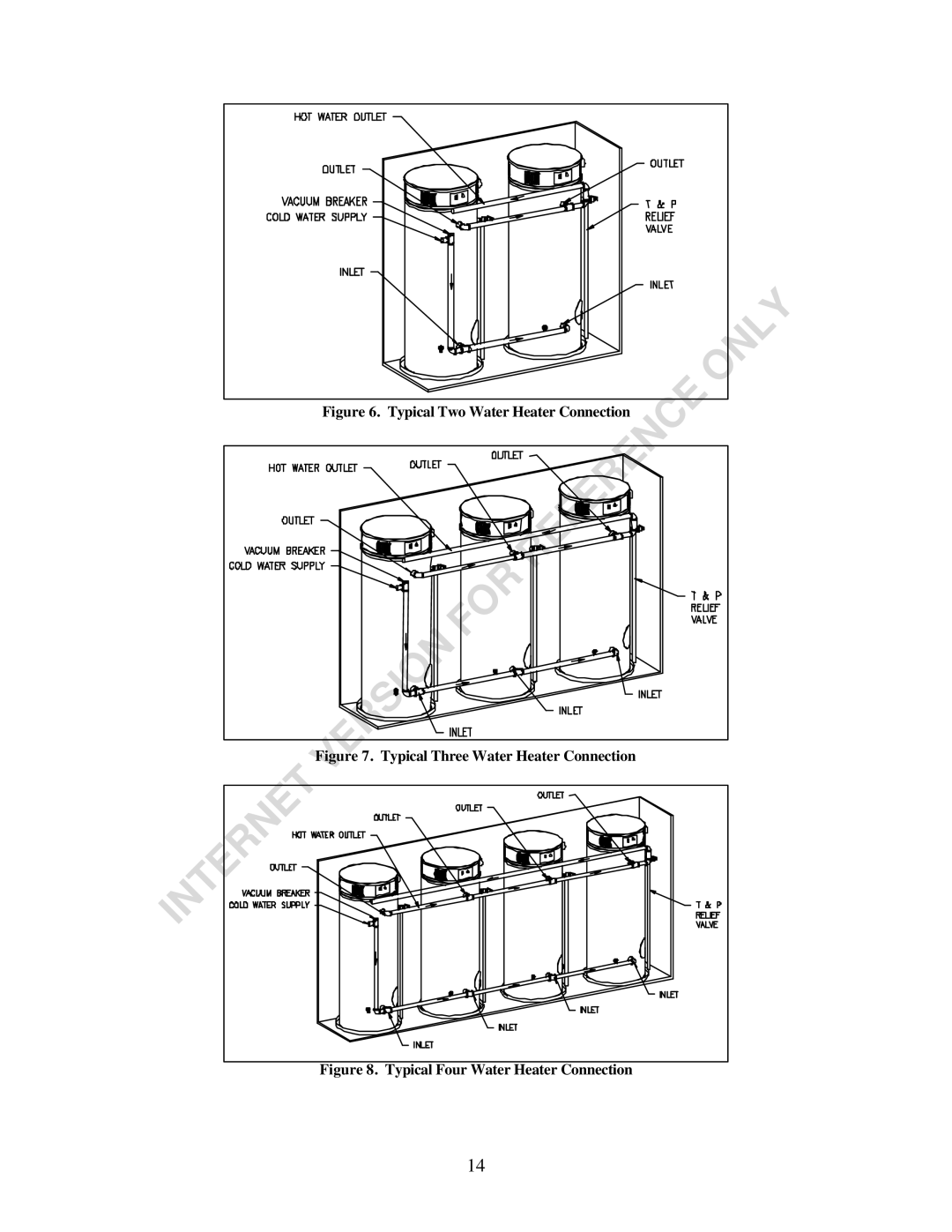
Figure 6. Typical Two Water Heater Connection
Figure 7. Typical Three Water Heater Connection
Figure 8. Typical Four Water Heater Connection
14
Page 13
Page 15
Page 14
Image 14
Page 13
Page 15
Contents
With Troubleshooting Guide
What to do if YOU Smell GAS
Table of Contents
Page
If YOU Smell GAS
Do not Operate the Appliance Until the Leakage is Corrected
Specifications
Section
Features
Section III General Information
Temperature and Pressure Relief Valve
Dishwashing Machine Requirements
Condensate Elbow With Loop
Section IV Installation Instructions
Unpacking
Minimum Clearance To Combustible
AIR Requ Rements
Location
Remove Crate
Confined Space
Mechanical Exhausting of Room AIR
Unconfined Space
Chemical Vapor Corrosion
Typical Installation Illustration
Typical Front Inlet Connection
Typical Two Water Heater Connection
Section V Water Connections
Instructions for Connections
Approximate TIME/TEMPERATURE Relationships in Scalds
Scalding
Alternate Space Heating Water Connections
Alternate Space Heating Connections
Typical Plumbing Schematic for Zoned Heating
Section VI Venting
Direct Vent Installation
Venting
Exceptions for Installations
Page
Typical Horizontal Direct Vent System
Typical Vertical Direct Vent System Installation
Power Vent Installation
Direct Vent Maximum Vent Length
Typical Horizontal Power Vent System
Typical Vertical Power Vent System Installation
Power Vent Maximum Vent Length
Coaxial Venting Installation Procedure
Dimensional Layout of Concentric Vent Kit
Concentric Vent Roof Top Attachment
Vent Pipe Preparation
Initial Preparation
Section VII GAS Connections
Selection of Materials
GAS Meter Size Natural Gases only
GAS Pressure Regulation
Wiring Diagram and Schematic
Section Viii Electrical Connections
To Fill the Water Heater
Section IX Operating Instructions
General Instructions
Sequence of Operation
Temperature Adjustm NT
Lighting Instructions
Burner Flame Check
Sight Glass Location
General
Section X Maintenance
Maintenance Schedule
Filling Water Heater
Flushing Water Heater
Draining Water Heater
Sediment and Lime Scale Removal
Relief Valve
Anode Inspection and Replacement
Drain Valve and Tank Access Panel
Vent and AIR Intake System
Combustion System Inspection
Section XI Troubleshooting Guide
Reference
Is there continuity across the Hot Surface Ignitor? If
Section XI Parts List
EF Series Water Heater
Combustion Surround Assy
CC Ignition Control Assy
Top
Page
Image
Contents