U1TW40S*FRN, U2TW65T*FRN, UTW450S60FR*N, U1TW60T*FRN, UTW465S60FR*N specifications
Bradford-White Corp has long been a reputable manufacturer in the water heating industry, known for delivering high-quality and reliable products. Among their diverse range of water heaters, the U1TW40S*FRN, U1TW50S*FRN, U1TW60T*FRN, UTW465S60FR*N, and UTW450S60FR*N models stand out for their advanced features and technologies designed to meet varying hot water demands.The U1TW series, including the U1TW40S*FRN, U1TW50S*FRN, and U1TW60T*FRN models, are well-suited for residential applications. Each model provides different capacities, with the numbers referring to the gallon capacities. The U1TW40S*FRN offers 40 gallons, the U1TW50S*FRN 50 gallons, and the U1TW60T*FRN 60 gallons, making them ideal for households varying in size and hot water requirements.
These models are equipped with Bradford-White's advanced Vitraglas® tank lining, a unique feature that provides superior protection against corrosion and extends the unit's lifespan by ensuring the inner tank remains free from damage. Additionally, their efficient heating elements and optimal insulation minimize heat loss, enhancing energy savings.
The UTW series, specifically the UTW465S60FR*N and UTW450S60FR*N, feature innovative technologies such as a durable stainless steel construction that offers robust performance while resisting the harmful effects of rust and degradation. This is particularly beneficial in areas with hard water, where mineral buildup can be problematic.
Each unit incorporates Bradford-White's signature HydroBurner® technology, which enhances combustion efficiency, ensuring that the water is heated quickly and consistently. This technology also helps in reducing greenhouse gas emissions, addressing environmental concerns while maintaining optimal performance.
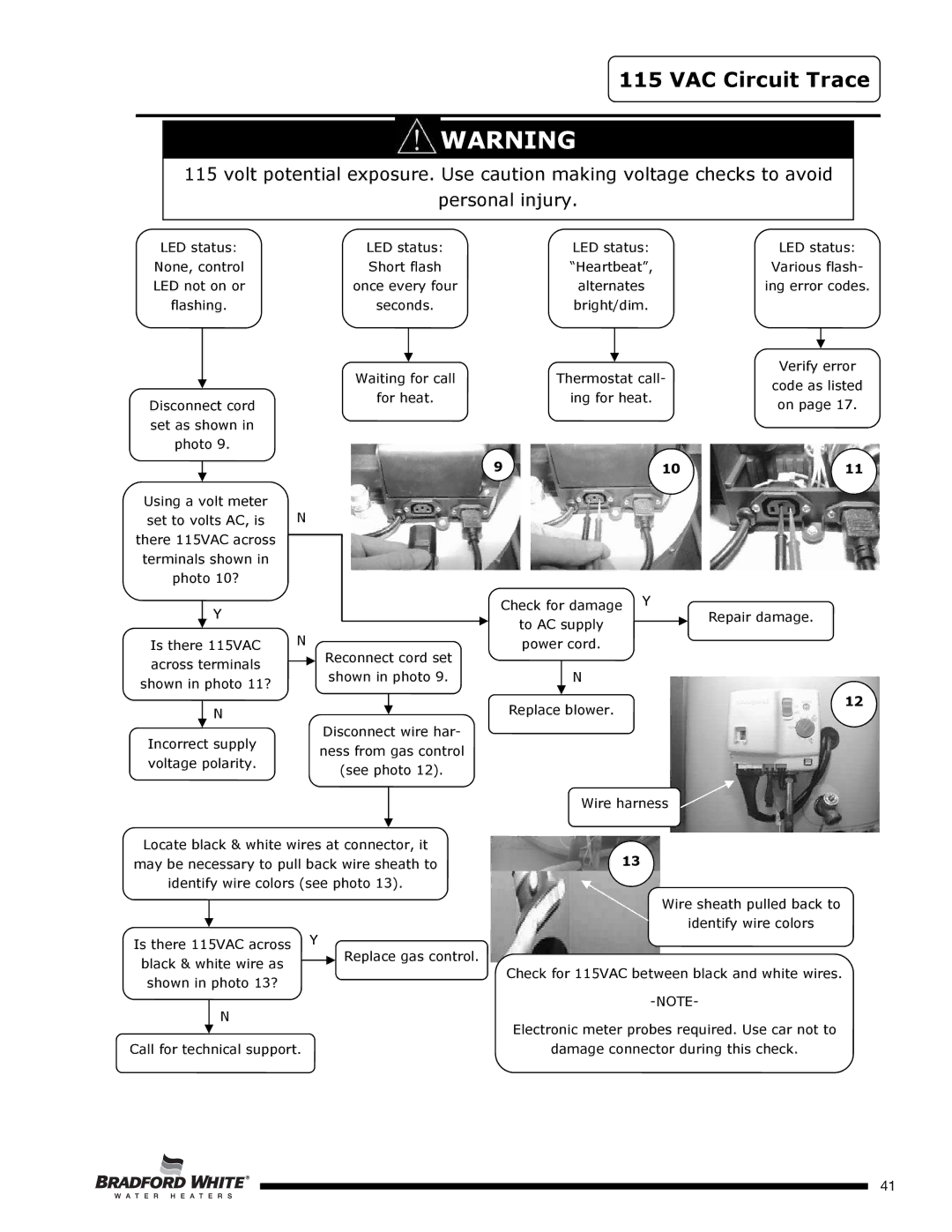
In terms of ease of use, all models come with user-friendly controls that allow for easy temperature adjustments and monitoring, ensuring that users can customize their hot water needs conveniently. Additionally, features such as intuitive diagnostics enable quick troubleshooting, reducing downtime and maintenance efforts.
In conclusion, Bradford-White’s U1TW and UTW series water heaters are engineered to offer efficiency, durability, and user-friendly operation. With their advanced technology, excellent insulation, and robust construction, these models are a solid choice for anyone looking to invest in reliable hot water solutions for their home. Whether for a busy family or more modest hot water needs, these units provide peace of mind and consistent performance.