Maintenance, Lubrication & Adjustments
Exterior Adjustments (continued)
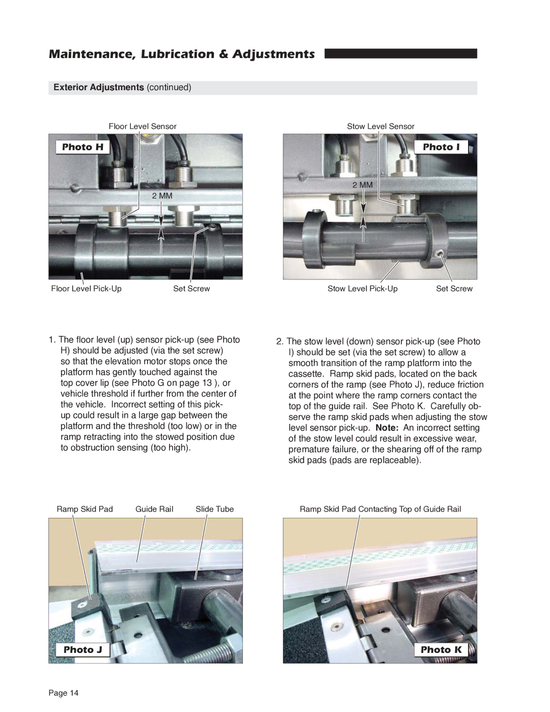
Floor Level Sensor
Photo H
2 MM
Stow Level Sensor
Photo I
2 MM
Floor Level | Set Screw | Stow Level | Set Screw |
1.The floor level (up) sensor
H)should be adjusted (via the set screw)
so that the elevation motor stops once the platform has gently touched against the top cover lip (see Photo G on page 13 ), or vehicle threshold if further from the center of the vehicle. Incorrect setting of this pick- up could result in a large gap between the platform and the threshold (too low) or in the ramp retracting into the stowed position due to obstruction sensing (too high).
2.The stow level (down) sensor
I)should be set (via the set screw) to allow a smooth transition of the ramp platform into the cassette. Ramp skid pads, located on the back corners of the ramp (see Photo J), reduce friction at the point where the ramp corners contact the top of the guide rail. See Photo K. Carefully ob- serve the ramp skid pads when adjusting the stow level sensor
Ramp Skid Pad | Guide Rail | Slide Tube | Ramp Skid Pad Contacting Top of Guide Rail |
Photo J
Page 14