Installation Instructions
User Inputs/Outputs
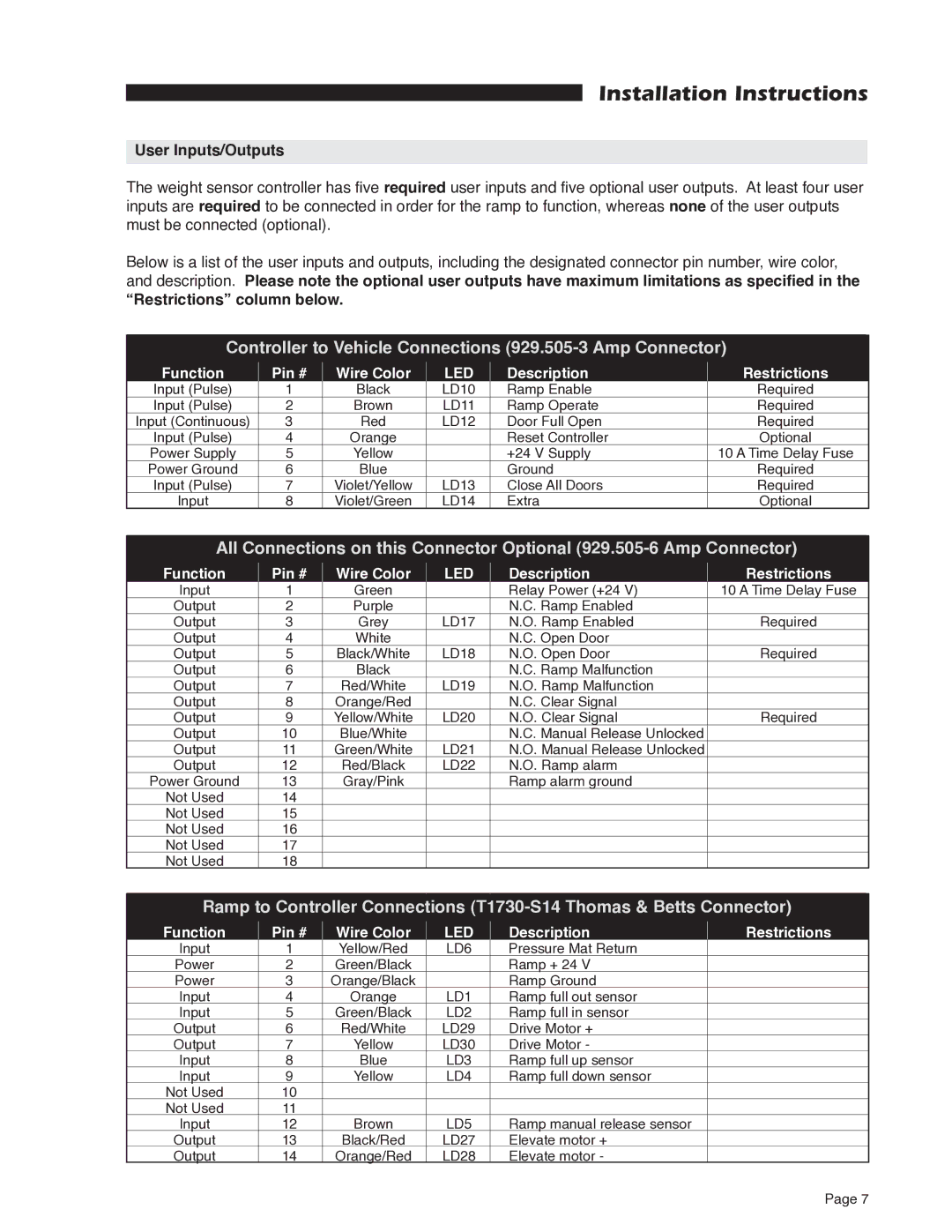
The weight sensor controller has five required user inputs and five optional user outputs. At least four user inputs are required to be connected in order for the ramp to function, whereas none of the user outputs must be connected (optional).
Below is a list of the user inputs and outputs, including the designated connector pin number, wire color, and description. Please note the optional user outputs have maximum limitations as specified in the “Restrictions” column below.
Controller to Vehicle Connections (929.505-3 Amp Connector)
Function | Pin # | Wire Color | LED | Description | Restrictions |
Input (Pulse) | 1 | Black | LD10 | Ramp Enable | Required |
Input (Pulse) | 2 | Brown | LD11 | Ramp Operate | Required |
Input (Continuous) | 3 | Red | LD12 | Door Full Open | Required |
Input (Pulse) | 4 | Orange |
| Reset Controller | Optional |
Power Supply | 5 | Yellow |
| +24 V Supply | 10 A Time Delay Fuse |
Power Ground | 6 | Blue |
| Ground | Required |
Input (Pulse) | 7 | Violet/Yellow | LD13 | Close All Doors | Required |
Input | 8 | Violet/Green | LD14 | Extra | Optional |
All Connections on this Connector Optional
Function | Pin # | Wire Color | LED | Description | Restrictions |
Input | 1 | Green |
| Relay Power (+24 V) | 10 A Time Delay Fuse |
Output | 2 | Purple |
| N.C. Ramp Enabled |
|
Output | 3 | Grey | LD17 | N.O. Ramp Enabled | Required |
Output | 4 | White |
| N.C. Open Door |
|
Output | 5 | Black/White | LD18 | N.O. Open Door | Required |
Output | 6 | Black |
| N.C. Ramp Malfunction |
|
Output | 7 | Red/White | LD19 | N.O. Ramp Malfunction |
|
Output | 8 | Orange/Red |
| N.C. Clear Signal |
|
Output | 9 | Yellow/White | LD20 | N.O. Clear Signal | Required |
Output | 10 | Blue/White |
| N.C. Manual Release Unlocked |
|
Output | 11 | Green/White | LD21 | N.O. Manual Release Unlocked |
|
Output | 12 | Red/Black | LD22 | N.O. Ramp alarm |
|
Power Ground | 13 | Gray/Pink |
| Ramp alarm ground |
|
Not Used | 14 |
|
|
|
|
Not Used | 15 |
|
|
|
|
Not Used | 16 |
|
|
|
|
Not Used | 17 |
|
|
|
|
Not Used | 18 |
|
|
|
|
Ramp to Controller Connections
Function | Pin # | Wire Color | LED | Description | Restrictions |
Input | 1 | Yellow/Red | LD6 | Pressure Mat Return |
|
Power | 2 | Green/Black |
| Ramp + 24 V |
|
Power | 3 | Orange/Black |
| Ramp Ground |
|
Input | 4 | Orange | LD1 | Ramp full out sensor |
|
Input | 5 | Green/Black | LD2 | Ramp full in sensor |
|
Output | 6 | Red/White | LD29 | Drive Motor + |
|
Output | 7 | Yellow | LD30 | Drive Motor - |
|
Input | 8 | Blue | LD3 | Ramp full up sensor |
|
Input | 9 | Yellow | LD4 | Ramp full down sensor |
|
Not Used | 10 |
|
|
|
|
Not Used | 11 |
|
|
|
|
Input | 12 | Brown | LD5 | Ramp manual release sensor |
|
Output | 13 | Black/Red | LD27 | Elevate motor + |
|
Output | 14 | Orange/Red | LD28 | Elevate motor - |
|
Page 7